


ASUS P2B-L/P2B-S/P2B-LS User’s Manual
11
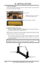
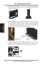
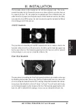
III. INSTALLATION
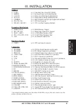
Jumpers
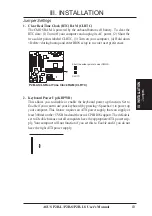
1) CLRTC
p. 13 Clear Real Time Clock (RTC) RAM
2) KBPWR
p. 13 Keyboard Power Up (Enable/Disable)
3) LAN_EN
p. 14 Onboard LAN Setting (Enable/Disable)
4) SCSI_EN
p. 14 Onboard SCSI Setting (Enable/Disable)
5) COMBINE
p. 14 IDE+SCSI LED Activity Light (Separated/Combined)
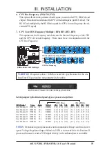
6) FS0, FS1, FS2
p. 15 CPU Bus Frequency
7) BF0, BF1, BF2, BF3
p. 15 CPU Core:Bus Frequency Multiple
Expansion Slots/Sockets
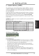
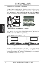
1) DIMM Sockets
p. 18 DIMM Memory Support
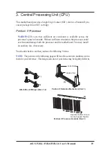
2) SEC CPU Slot
p. 19 Single Edge Contact CPU Support
3) SLOT1, SLOT2
p. 24 16-bit ISA Bus Expansion Slots
*
4) PCI1, PCI2, PCI3, PCI4
p. 25 32-bit PCI Bus Expansion Slots
†
5) AGP
p. 25 Accelerated Graphics Port
Hardware Monitor
1) TRCPU
p. 22 CPU heat Sensor Connector
Connectors
1) PS2KBMS
p. 26 PS/2 Keyboard Connector (6-pin female)
2) PS2KBMS
p. 26 PS/2 Mouse Connector (6-pin female)
3) PRINTER
p. 27 Parallel (Printer) Port Connector (25-pin female)
4) COM1/COM2
p. 27 Serial Port COM1/COM2 (two 9-pin male)
5) RJ-45
p. 27 RJ-45 Connector (8-pin female)
6) USB
p. 28 Universal Serial BUS Ports 1 & 2 (two 4 pin female)
7) A
p. 28 LAN Condition Connector (6 pins)
8) FLOPPY
p. 28 Floppy Drive Connector (34-1 pins)
9) Primary/Secondary IDE
p. 29 Primary/Secondary IDE Connector (40 pins)
10) IDELED/SCSILED
p. 29 IDE/SCSI LED Activity Light (two 2 pins)
11) SCSI-50/SCSI-68/ULTRA2-68 p. 30 Ultra-Fast (50)/Wide (68)/Ultra2 (68) SCSI Connectors
12) IR
p. 31 Infrared Port Module Connector (5 pins)
13) SBLINK
p. 31 SB-LINK™ Connector (6-1 pins)
14) TB LED (PANEL)
p. 32 Message LED Lead (2 pins)
15) SMI (PANEL)
p. 32 SMI Suspend Switch Lead (2 pins)
16) PWR (PANEL)
p. 32 ATX Power Switch / Soft Power Switch (2 pins)
17) RESET (PANEL)
p. 32 Reset Switch Lead (2 pins)
18) KEYLOCK (PANEL)
p. 32 System Power LED (3 pins)
19) KEYLOCK (PANEL)
p. 32 Keyboard Lock Switch Lead (2 pins)
20) SPEAKER (PANEL)
p. 32 Speaker Connector (4 pins)
21) CHASSIS
p. 33 Chassis Open Alarm Lead (4-1 pins)
22) CHA_/CPU_/PWR_FAN
p. 33 Chassis/CPU/Power Supply Fan Connectors (3 pins)
23) ATXPWR
p. 34 ATX Motherboard Power Connector (20 pins)
*
The onboard hardware monitor uses the address 290H-297H so legacy ISA cards must not use this
address, otherwise conflicts will occur.
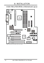
Board Layout
III. INST
ALLA
TION
Содержание P2B-L
Страница 8: ......
Страница 16: ...16 ASUS P2B L P2B S P2B LS User s Manual This page was intentionally left blank ...
Страница 32: ......
Страница 46: ......
Страница 78: ...78 ASUS P2B L P2B S P2B LS User s Manual This page was intentionally left blank ...
Страница 87: ...ASUS P2B L P2B S P2B LS User s Manual 87 This page was intentionally left blank ...
Страница 88: ...88 ASUS P2B L P2B S P2B LS User s Manual This page was intentionally left blank ...


