background image

7

Installation manual

English

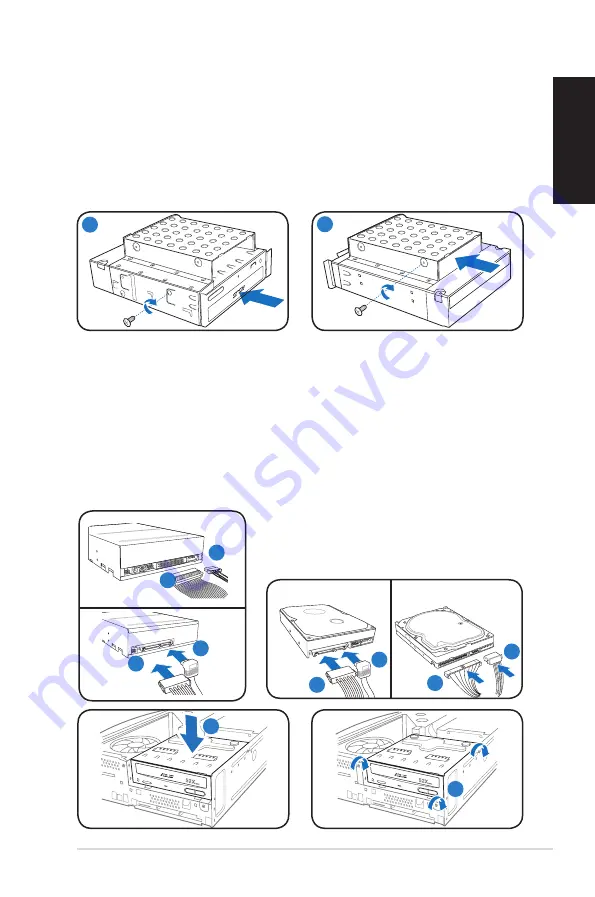
Installing optical and storage drives

1.  Turn the storage drive assembly upside down with the 3.5-inch bay on top of 

the 5.25-inch bay.

2.  Insert the optical drive upside down to the 5.25-inch bay, then secure it with 

two screws on both sides.

3.  Turn the storage drive assembly, insert the hard disk drive upside down to the 

3.5-inch bay, then secure it with two screws on both sides.

Reinstalling the storage drive assembly

1.  Connect the SATA/IDE (1A) and power (1B) plugs to connectors at the back 

of the optical drive.

2.  Connect the SATA/IDE (2A) and power (2B) plugs to the connectors at the 

back of the SATA/IDE hard disk drives.

3.  Install the storage drive assembly to the chassis.
4.  Secure the storage drive assembly with three screws.

1A

1B

SATA

IDE

2A

2B

2A

2B

2

3

R

3

R

4

1B

1A

SATA

IDE

Содержание P2-M2A690G - P Series - 0 MB RAM

Страница 1: ...English P Series ASUS PC Desktop Barebone Installation manual E4233 Download the latest manual from the ASUS website www asus com P2 P4 ...

Страница 2: ...d port PS 2 mouse port VGA port HDMI port Parallel port USB 2 0 ports LAN RJ 45 port Serial COM1 port DVI D port Optical S PDIF Out port Coaxial S PDIF Out port Audio ports configurations 6 channel 8 channel 14 Expansion slot metal brackets P2 Front Close Front Open NOTE The front rear panel slots ports and their locations may vary depending on the model of your system For detailed descriptions re...

Страница 3: ...moving the cover 1 Remove the cover screws on the rear panel Keep the screws for later use 2 Pull the cover toward the rear panel 3 Lift the cover then set it aside 1 Locate the front panel cover hooks then lift them until they disengage from the chasis 2 Swing the front panel cover to the right remove it and set it aside Removing the front panel cover R 2 1 2 3 1 Removing the storage drive assemb...

Страница 4: ... the bottom left corner of the socket Fit the socket alignment key into the CPU notch 6 Close the load plate 6A then push the load lever 6B until it snaps into the retention tab Load lever Retention tab A B Gold triangle mark Alignment key 6B 6A Load plate PnP cap 4B 4A 3 Installing an Intel CPU heatsink and fan 1 Place the heatsink on top of the installed CPU making sure that the four fasteners m...

Страница 5: ... then remove the fan and heatsink assembly Retention module Locking levers 2 1 5 Installing an AMD CPU 1 Locate the CPU socket then lift the socket lever to a 90º angle 2 Install the CPU to the socket making sure that the CPU corner with the gold triangle matches the socket corner with a small triangle 3 Push down the socket lever to secure the CPU 1 2 3 NOTE To reinstall AMD CPU fan and heatsink ...

Страница 6: ...ket such that the notch on the DIMM matches the break on the socket 4 Push the DIMM to the socket until the retaining clips snap inward CAUTION Unplug the power supply before adding or removing DIMMs Failure to do so may cause damage to the motherboard and or components A DDR DIMM is keyed with a notch so that it fits in only one direction Do not force a DIMM into a socket to avoid damaging the DI...

Страница 7: ...insert the hard disk drive upside down to the 3 5 inch bay then secure it with two screws on both sides Reinstalling the storage drive assembly 1 Connect the SATA IDE 1A and power 1B plugs to connectors at the back of the optical drive 2 Connect the SATA IDE 2A and power 2B plugs to the connectors at the back of the SATA IDE hard disk drives 3 Install the storage drive assembly to the chassis 4 Se...

Страница 8: ... the lock then slightly push the foot stand to the direction of the rear panel until it disengages from the chassis Reinstalling the cover 1 Insert the cover to the chasis Make sure the cover tabs fit the chasis rails 2 Push the cover toward the front panel until it fits in place 3 Secure the cover with two screws you removed earlier Reinstalling the front panel cover NOTE Refer to the pictures in...

Отзывы: