background image

ASUS P5PL2-E

2-15

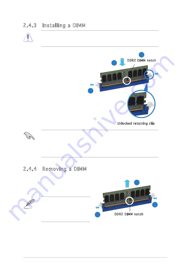
2.4.3  Installing a DIMM

Unplug the power supply before adding or removing DIMMs or other 

system components. Failure to do so can cause severe damage to both 

the motherboard and the components.

To install a DIMM:

1.  Unlock a DIMM socket by pressing
 

 the retaining clips outward.

2.  Align a DIMM on the socket 
 

such that the notch on the 


DIMM matches the break on 


the socket.

3.  Firmly insert the DIMM into the 
 

socket until the retaining clips snap


back in place and the DIMM is properly seated.

2.4.4  Removing a DIMM

Follow these steps to remove a DIMM.

1.  Simultaneously press the retaining 
 

clips outward to unlock the DIMM.

2.  Remove the DIMM from the socket.

•  A DDR2 DIMM is keyed with a notch so that it fits in only one 

direction. Do not force a DIMM into a socket to avoid damaging the 

DIMM.

•  The DDR2 DIMM sockets do not support DDR DIMMs. DO not install 

DDR DIMMs to the DDR2 DIMM sockets.

Unlocked retaining clip

DDR2 DIMM notch

Support the DIMM lightly with  

your fingers when pressing 

the retaining clips. The DIMM  

might get damaged when it 

flips out with extra force.

DDR2 DIMM notch

1

2

3

1

2

1

Содержание Motherboard P5PL2-E

Страница 1: ...Motherboard P5PL2 E ...

Страница 2: ...RCHANTABILITY OR FITNESS FOR A PARTICULAR PURPOSE IN NO EVENT SHALL ASUS ITS DIRECTORS OFFICERS EMPLOYEES OR AGENTS BE LIABLE FOR ANY INDIRECT SPECIAL INCIDENTAL OR CONSEQUENTIAL DAMAGES INCLUDING DAMAGES FOR LOSS OF PROFITS LOSS OF BUSINESS LOSS OF USE OR DATA INTERRUPTION OF BUSINESS AND THE LIKE EVEN IF ASUS HAS BEEN ADVISED OF THE POSSIBILITY OF SUCH DAMAGES ARISING FROM ANY DEFECT OR ERROR IN...

Страница 3: ...les 2 2 2 2 3 Motherboard layout 2 3 2 2 4 Layout contents 2 4 2 3 Central Processing Unit CPU 2 6 2 3 1 Installing the CPU 2 6 2 3 2 Installing the CPU heatsink and fan 2 9 2 3 3 Uninstalling the CPU heatsink and fan 2 11 2 4 System memory 2 13 2 4 1 Overview 2 13 2 4 2 Memory configurations 2 13 2 4 3 Installing a DIMM 2 15 2 4 4 Removing a DIMM 2 15 2 5 Expansion slots 2 16 2 5 1 Installing an ...

Страница 4: ... ASUS CrashFree BIOS 2 utility 4 5 4 1 4 ASUS EZ Flash utility 4 7 4 1 5 ASUS Update utility 4 8 4 2 BIOS setup program 4 11 4 2 1 Menu bar 4 12 4 2 2 Navigation keys 4 12 4 2 3 BIOS menu screen 4 12 4 2 4 Menu items 4 13 4 2 5 Sub menu items 4 13 4 2 6 Configuration fields 4 13 4 2 7 Pop up window 4 13 4 2 8 Scroll bar 4 13 4 2 9 General help 4 13 4 3 Main menu 4 14 4 3 1 System Time 4 14 4 3 2 S...

Страница 5: ...4 35 4 6 2 Boot Settings Configuration 4 36 4 6 3 Security 4 37 4 7 Exit menu 4 40 Chapter 5 Software support 5 1 Installing an operating system 5 1 5 2 Support CD information 5 1 5 2 1 Running the support CD 5 1 5 2 2 Drivers menu 5 2 5 2 3 Utilities menu 5 3 5 2 4 Manuals menu 5 4 5 2 5 Contact information 5 5 5 2 6 Other information 5 5 5 3 ASUS MyLogo 5 7 Appendix CPU features A 1 Intel EM64T ...

Страница 6: ...ause harmful interference to radio or television reception which can be determined by turning the equipment off and on the user is encouraged to try to correct the interference by one or more of the following measures Reorient or relocate the receiving antenna Increase the separation between the equipment and receiver Connect the equipment to an outlet on a circuit different from that to which the...

Страница 7: ...your area If you are not sure about the voltage of the electrical outlet you are using contact your local power company If the power supply is broken do not try to fix it by yourself Contact a qualified service technician or your retailer Operation safety Before installing the motherboard and adding devices on it carefully read all the manuals that came with the package Before using the product ma...

Страница 8: ...the system Chapter 4 BIOS setup This chapter tells how to change system settings through the BIOS Setup menus Detailed descriptions of the BIOS parameters are also provided Chapter 5 Software support This chapter describes the contents of the support CD that comes with the motherboard package Appendix CPU features The Appendix describes the CPU features that the motherboard supports Where to find ...

Страница 9: ...2 Key3 If you must press two or more keys simultaneously the key names are linked with a plus sign Example Ctrl Alt D Command Means that you must type the command exactly as shown then supply the required item or value enclosed in brackets Example At the DOS prompt type the command line afudos i filename afudos iP5PL2 E ROM DANGER WARNING Information to prevent injury to yourself when trying to co...

Страница 10: ...outh Bridge supports 1 x Ultra DMA 100 66 33 4 x Serial ATA 3Gb s devices ADI 1986A 6 channel audio Supports Jack Sensing and Enumeration Technology S PDIF out interface Supports up to 8 USB 2 0 USB 1 1 ports RTL8111B 1000 100 10 Ethernet LAN ASUS C P R CPU Parameter Recall Adjustable CPU voltage at 0 0125 V increment SFS Stepless Frenquency Selection from 200 MHz up to 450 MHz at 1MHz increment 4...

Страница 11: ...onnectors WOL by PME WOR by PME WOR by Ring WO_USB WO_KB MS WOW Drivers ASUS PC Probe II ASUS LiveUpdate Utility Adobe Acrobat Reader ver 7 0 Microsoft Direct X ver 9 0C ASUS AI Booster 2 x SATA cable kit 1 x USB 2 0 cable 1 x UltraDMA 100 66 33 cable 1 x I O Shield User s manual ATX Form Factor 12 x7 5 30 5cm x 19cm P5PL2 E specifications summary Internal I O connectors Manageability Support CD c...

Страница 12: ...xii ...

Страница 13: ...1 Product introduction This chapter describes the motherboard features and the new technologies it supports ...

Страница 14: ...ASUS P5PL2 E Chapter summary 1 1 1 Welcome 1 1 1 2 Package contents 1 1 1 3 Special features 1 2 ...

Страница 15: ...ard and hardware devices on it check the items in your package with the list below 1 2 Package contents Check your motherboard package for the following items Motherboard ASUS P5PL2 E motherboard I O modules USB 2 0 2 ports module Cables 1 x 3 in 1 ATA FDD cable 2 x SATA cables 2 x SATA power cables Accessories I O shield Application CDs ASUS motherboard support CD Documentation User guide If any ...

Страница 16: ...and increased productivity This motherboard provides excellent compatibility and flexibility by supporting either 64 bit or 32 bit architecture Dual Channel DDRII 533 DDR2 is the next generation memory technology to replace the current DDR With initial speeds of 400 and 533MHz DDR2 memory provides bandwidth up to 4 3GB s Doubled by the dual channel architecture the widest memory bus bandwidth 8 6G...

Страница 17: ...e flexibility when increasing external FSB 1 3 2 Innovative ASUS features C P R CPU Parameter Recall The C P R feature of the motherboard BIOS allows automatic re setting to the BIOS default settings in case the system hangs due to overclocking When the system hangs due to overclocking C P R eliminates the need to open the system chassis and clear the RTC data Simply shut down and reboot the syste...

Страница 18: ...1 Chapter 1 Product introduction ...

Страница 19: ... Hardware information This chapter lists the hardware setup procedures that you have to perform when installing system components It includes description of the jumpers and connectors on the motherboard ...

Страница 20: ...S P5PL2 E Chapter summary 2 2 1 Before you proceed 2 1 2 2 Motherboard overview 2 2 2 3 Central Processing Unit CPU 2 6 2 4 System memory 2 13 2 5 Expansion slots 2 16 2 6 Jumpers 2 19 2 7 Connectors 2 21 ...

Страница 21: ...ord from the wall socket before touching any component Use a grounded wrist strap or touch a safely grounded object or to a metal object such as the power supply case before handling components to avoid damaging them due to static electricity Hold components by the edges to avoid touching the ICs on them Whenever you uninstall any component place it on a grounded antistatic pad or in the bag that ...

Страница 22: ...sical injury and damage motherboard components Do not overtighten the screws Doing so can damage the motherboard 2 2 1 Placement direction When installing the motherboard make sure that you place it into the chassis in the correct orientation The edge with external ports goes to the rear part of the chassis as indicated in the image below 2 2 2 Screw holes Place six 6 screws into the holes indicat...

Страница 23: ...E LGA775 CPU_FAN Super I O EATXPWR SATA1 SATA2 SATA4 SATA3 Intel ICH7 Intel MCH 945 PCI1 PRI_EIDE CHA_FAN PANEL CHASSIS SPDIF_OUT SB_PWR USBPW56 USBPW78 FLOPPY PCI2 PCI3 PCIEX1_1 PCIEX1_2 PCIEX16 GAME USB56 USB78 AAFP CD ATX12V 4Mb BIOS PWR_FAN CR2032 3V Lithium Cell CMOS Power CLRTC USBPW34 USBPW12 AUDIO LAN_USB34 USB12 e PS 2KBMS T Mouse B K yboard SPDIF_O1 PARALLE PORT COM1 AD1986A RTL8111B ICS...

Страница 24: ...up 3 pin USBPW12 USBPW34 2 21 USBPW56 USBPW78 Rear panel connectors Page 1 PS 2 mouse port green 2 22 2 Parallel port 2 22 3 LAN RJ 45 port 2 22 4 Line In port light blue 2 22 5 Line Out port lime 2 22 6 Microphone port pink 2 22 7 USB 2 0 ports 3 and 4 2 23 8 USB 2 0 ports 1 and 2 2 23 9 Serial port COM1 2 23 10 Coaxial S PDIF Out port 2 23 11 PS 2 keyboard port purple 2 23 ...

Страница 25: ...1 pin AAFP 2 25 7 USB connectors 10 1 pin USB56 USB78 2 26 8 GAME MIDI port connector 16 1 pin GAME 2 26 9 CPU Chassis and Power Fan connectors 4 pin CPU_FAN 2 27 3 pin CHA_FAN1 PWR_FAN 10 Chassis intrusion connector 4 1 pin CHASSIS 2 27 11 ATX power connectors 24 pin EATXPWR 4 pin ATX12V 2 28 12 System panel connector 20 1 pin PANEL 2 29 System power LED Green 3 pin PLED Hard disk drive activity ...

Страница 26: ...on the socket and the socket contacts are not bent Contact your retailer immediately if the PnP cap is missing or if you see any damage to the PnP cap socket contacts motherboard components ASUS will shoulder the cost of repair only if the damage is shipment transit related Keep the cap after installing the motherboard ASUS will process Return Merchandise Authorization RMA requests only if the mot...

Страница 27: ...ure that the gold triangle is on the bottom left corner of the socket The socket alignment key should fit into the CPU notch Alignment key Gold triangle mark Load plate A B 2 Press the load lever with your thumb A then move it to the left B until it is released from the retention tab Retention tab Load lever This side of the socket box should face you PnP cap A B To prevent damage to the socket pi...

Страница 28: ...t and damaging the CPU 6 Close the load plate A then push the load lever B until it snaps into the retention tab A B The motherboard supports Intel Pentium 4 LGA775 processors with the Intel Enhanced Memory 64 Technology EM64T Enhanced Intel SpeedStep Technology EIST and Hyper Threading Technology Refer to the Appendix for more information on these CPU features ...

Страница 29: ...ke sure that you use only Intel certified multi directional heatsink and fan Your Intel Pentium D LGA775 heatsink and fan assembly comes in a push pin design and requires no tool to install If you purchased a separate CPU heatsink and fan assembly make sure that you have properly applied Thermal Interface Material to the CPU heatsink or CPU before you install the heatsink and fan assembly Make sur...

Страница 30: ...ush down two fasteners at a time in a diagonal sequence to secure the heatsink and fan assembly in place B B A A A A B B Do not forget to connect the CPU fan connector Hardware monitoring errors can occur if you fail to plug this connector P5PL2 E P5PL2 E CPU Fan Connector CPU_FAN GND CPU FAN PWR CPU FAN IN CPU FAN PWM ...

Страница 31: ...nnect the CPU fan cable from the connector on the motherboard 2 Rotate each fastener counterclockwise 3 Pull up two fasteners at a time in a diagonal sequence to disengage the heatsink and fan assembly from the motherboard B B A A A A B B 4 Carefully remove the heatsink and fan assembly from the motherboard ...

Страница 32: ... orientation when reinstalling The narrow end of the groove should point outward after resetting The photo shows the groove shaded for emphasis Narrow end of the groove Refer to the documentation in the boxed or stand alone CPU fan package for detailed information on CPU fan installation ...

Страница 33: ...1 GB unbuffered non ECC DDR2 DIMMs into the DIMM sockets For dual channel configuration the total size of memory module s installed per channel must be the same DIMM_A1 DIMM_A2 DIMM_B1 DIMM_B2 Always install DIMMs with the same CAS latency For optimum compatibility it is recommended that you obtain memory modules from the same vendor Refer to the DDR2 Qualified Vendors List on the next page for de...

Страница 34: ... DDR2 533 400 MHz QVL 256 MB Kingston KVR533D2N4 256 N A Elpida SS E5116AB 5C E 512 MB Kingston KVR533D2N4 512 N A Hynix DS HY5PS56821 1 G Kingston KVR533D2N4 1G N A Kingston DS D6408TE7BL 37 256 MB Samsung M378T3253FG0 CD5 N A Samsung SS K4T560838QF GCD5 512 MB Samsung M378T6553BG0 CD5 N A Samsung SS K4T51083QB GCD5 512 MB Infineon HYS64T64000GU 3 7 A N A Infineon SS HYB18T512800AC37SSS11511 512 ...

Страница 35: ... snap back in place and the DIMM is properly seated 2 4 4 Removing a DIMM Follow these steps to remove a DIMM 1 Simultaneously press the retaining clips outward to unlock the DIMM 2 Remove the DIMM from the socket A DDR2 DIMM is keyed with a notch so that it fits in only one direction Do not force a DIMM into a socket to avoid damaging the DIMM The DDR2 DIMM sockets do not support DDR DIMMs DO not...

Страница 36: ...cure the card to the chassis with the screw you removed earlier 6 Replace the system cover 2 5 2 Configuring an expansion card After installing the expansion card configure the it by adjusting the software settings 1 Turn on the system and change the necessary BIOS settings if any See Chapter 4 for information on BIOS setup 2 Assign an IRQ to the card Refer to the tables on the next page 3 Install...

Страница 37: ...ing 12 7 PS 2 Compatible Mouse Port 13 8 Numeric Data Processor 14 9 Primary IDE Channel 15 10 Secondary IDE Channel These IRQs are usually available for ISA or PCI devices IRQ assignments for this motherboard A B C D E F G H PCI slot 1 shared PCI slot 2 shared PCI slot 3 shared PCI E x16 slot shared PCI E x1 slot 1 shared PCI E x1 slot 2 shared Onboard USB controller 0 shared Onboard USB controll...

Страница 38: ...xpress x16 slot This motherboard supports PCI Express x16 graphic cards that comply with the PCI Express specifications The following figure shows a graphics card installed on the PCI Express x16 slot 2 5 6 PCI Express x1 slot This motherboard supports PCI Express x1 network cards SCSI cards and other cards that comply with the PCI Express specifications The following figure shows a network card i...

Страница 39: ...Keep the cap on pins 2 3 for about 5 10 seconds then move the cap back to pins 1 2 4 Re install the battery 5 Plug the power cord and turn ON the computer 6 Hold down the Del key during the boot process and enter BIOS setup to re enter data Except when clearing the RTC RAM never remove the cap on CLRTC jumper default position Removing the cap will cause system boot failure You do not need to clear...

Страница 40: ... The USBPWR12 and USBPWR34 jumpers are for the rear USB ports The USBPWR56 and USBPWR78 jumpers are for the internal USB connectors that you can connect to additional USB ports The USB device wake up feature requires a power supply that can provide 500mA on the 5VSB lead for each USB port otherwise the system would not power up The total current consumed must NOT exceed the power supply capability...

Страница 41: ...ort light blue This port connects a tape CD DVD player or other audio sources 5 Line Out port lime This port connects a headphone or a speaker In 4 channel 6 channel and 8 channel configuration the function of this port becomes Front Speaker Out 6 Microphone port pink This port connects a microphone ACT LINK LED SPEED LED Status Description Status Description OFF No link OFF 10 Mbps connection GRE...

Страница 42: ...In Line In Line In Lime Line Out Front Speaker Out Front Speaker Out Front Speaker Out Pink Mic In Mic In Mic In Mic In Port 2 channel 4 channel 6 channel 8 channel Headset Refer to the audio configuration table below for the function of the audio ports in 2 4 6 or 8 channel configuration 2 7 2 Internal connectors 1 Floppy disk drive connector 34 1 pin FLOPPY This connector is for the provided flo...

Страница 43: ...d disk documentation for the jumper settings Pin 20 on the IDE connector is removed to match the covered hole on the Ultra DMA cable connector This prevents incorrect insertion when you connect the IDE cable Use the 80 conductor IDE cable for Ultra DMA 100 66 IDE devices P5PL2 E P5PL2 E IDE Connector NOTE Orient the red markings usually zigzag on the ID ribbon cable to PIN 1 PRI_IDE PIN1 3 Digital...

Страница 44: ...E mode connect the primary boot hard disk drive to the SATA1 or SATA2 connector Refer to the table below for the recommended SATA hard disk drive connections Serial ATA hard disk drive connection Connector Color Setting Use SATA1 SATA2 Red Master Boot disk SATA3 SATA4 Black Slave Data disk P5PL2 E P5PL2 E SATA Connectors GND RSA TA_TXP1 RSA TA_TXN1 GND RSA TA_RXP1 RSA TA_RXN1 GND GND RSA TA_TXP4 R...

Страница 45: ...inition audio capability 5 Optical drive audio connector 4 pin CD This connector is for the 4 pin audio cable that connects to the audio connector at the back of the optical drive P5PL2 E P5PL2 E Internal Audio Connector CD black Right Audio Channel Left Audio Channel Ground Ground P5PL2 E P5PL2 E Front Panel Audio Connector HP_HD MIC2_L HP_R HP_L MIC2_JD Jack_Sense MIC2_R PRESENSE AGND AAFP Legac...

Страница 46: ...onnector is for a GAME MIDI port Connect the USB GAME module cable to this connector then install the module to a slot opening at the back of the system chassis The GAME MIDI port connects a joystick or game pad for playing games and MIDI devices for playing or editing audio files P5PL2 E P5PL2 E USB 2 0 Connectors USB78 USB 5V USB_P8 USB_P8 GND NC USB 5V USB_P7 USB_P7 GND 1 USB56 USB 5V USB_P6 US...

Страница 47: ...caps on the fan connectors 10 Chassis intrusion connector 4 1 pin CHASSIS This connector is for a chassis mounted intrusion detection sensor or switch Connect one end of the chassis intrusion sensor or switch cable to this connector The chassis intrusion sensor or switch sends a high level signal to this connector when a chassis component is removed or replaced The signal is then generated as a ch...

Страница 48: ...er of 350 W is recommended for a fully configured system Do not forget to connect the 4 pin ATX 12 V power plug otherwise the system will not boot up Use of a PSU with a higher power output is recommended when configuring a system with more power consuming devices The system may become unstable or may not boot up if the power is inadequate P5PL2 E P5PL2 E ATX Power Connector EATXPWR 3 Volts 3 Volt...

Страница 49: ...gs ATX power button soft off button Yellow 2 pin PWRSW This connector is for the system power button Pressing the power button turns the system on or puts the system in sleep or soft off mode depending on the BIOS settings Pressing the power switch for more than four seconds while the system is ON turns the system OFF Reset button Blue 2 pin RESET This 2 pin connector is for the chassis mounted re...

Страница 50: ...2 30 Chapter 2 Hardware information ...

Страница 51: ...3 Powering up This chapter describes the power up sequence the vocal POST messages and ways of shutting down the system ...

Страница 52: ...ASUS P5PL2 E Chapter summary 3 3 1 Starting up for the first time 3 1 3 2 Powering off the computer 3 2 ...

Страница 53: ...or if it has a power standby feature the monitor LED may light up or switch between orange and green after the system LED turns on The system then runs the power on self tests or POST While the tests are running the BIOS beeps see BIOS beep codes table below or additional messages appear on the screen If you do not see anything within 30 seconds from the time you turned on the power the system may...

Страница 54: ...ndows XP 1 Click the Start button then select Turn Off Computer 2 Click the Turn Off button to shut down the computer 3 The power supply should turn off after Windows shuts down 3 2 2 Using the dual function power switch While the system is ON pressing the power switch for less than four seconds puts the system to sleep mode or to soft off mode depending on the BIOS setting Pressing the power swit...

Страница 55: ...4 BIOS setup This chapter tells how to change the system settings through the BIOS Setup menus Detailed descriptions of the BIOS parameters are also provided ...

Страница 56: ...ASUS P5PL2 E Chapter summary 4 4 1 Managing and updating your BIOS 4 1 4 2 BIOS setup program 4 11 4 3 Main menu 4 14 4 4 Advanced menu 4 19 4 5 Power menu 4 30 4 6 Boot menu 4 35 4 7 Exit menu 4 40 ...

Страница 57: ...4 1 1 Creating a bootable floppy disk 1 Do either one of the following to create a bootable floppy disk DOS environment a Insert a 1 44MB floppy disk into the drive b At the DOS prompt type format A S then press Enter Windows XP environment a Insert a 1 44 MB floppy disk to the floppy disk drive b Click Start from the Windows desktop then select My Computer c Select the 3 1 2 Floppy Drive icon d C...

Страница 58: ...eld type D bootdisk makeboot a assuming that D is your optical drive letter e Press Enter then follow screen instructions to continue 2 Copy the original or the latest motherboard BIOS file to the bootable floppy disk Main filename Extension name 1 Copy the AFUDOS utility afudos exe from the motherboard support CD to the bootable floppy disk you created earlier 2 Boot the system in DOS mode then a...

Страница 59: ...fudos exe from the motherboard support CD to the bootable floppy disk you created earlier 3 Boot the system in DOS mode then at the prompt type afudos i filename where filename is the latest or the original BIOS file on the bootable floppy disk Updating the BIOS file To update the BIOS file using the AFUDOS utility 1 Visit the ASUS website www asus com and download the latest BIOS file for the mot...

Страница 60: ...ading flash done Advance Check Erasing flash done Writing flash 0x0008CC00 9 4 The utility verifies the file and starts updating the BIOS Do not shut down or reset the system while updating the BIOS to prevent system boot failure A afudos iP5PL2E rom AMI Firmware Update Utility Version 1 19 ASUS V2 07 03 11 24BB Copyright C 2002 American Megatrends Inc All rights reserved WARNING Do not turn off p...

Страница 61: ...lowing message and automatically checks the floppy disk for the original or updated BIOS file Bad BIOS checksum Starting BIOS recovery Checking for floppy 4 Restart the system after the utility completes the updating process Bad BIOS checksum Starting BIOS recovery Checking for floppy Floppy found Reading file P5PL2E rom Completed Start flashing When found the utility reads the BIOS file and start...

Страница 62: ...ically checks the floppy disk for the original or updated BIOS file 4 Restart the system after the utility completes the updating process DO NOT shut down or reset the system while updating the BIOS Doing so can cause system boot failure Bad BIOS checksum Starting BIOS recovery Checking for floppy Floppy not found Checking for CD ROM CD ROM found Reading file P5PL2E rom Completed Start flashing Wh...

Страница 63: ... POST to display the following EZFlash starting BIOS update Checking for floppy 4 Insert the floppy disk that contains the BIOS file to the floppy disk drive When the correct BIOS file is found EZ Flash performs the BIOS update process and automatically reboots the system when done EZFlash starting BIOS update Checking for floppy Floppy found Reading file P5PL2E rom Completed Start erasing Start p...

Страница 64: ...to manage save and update the motherboard BIOS in Windows environment The ASUS Update utility allows you to Save the current BIOS file Download the latest BIOS file from the Internet Update the BIOS from an updated BIOS file Update the BIOS directly from the Internet and View the BIOS version information This utility is available in the support CD that comes with the motherboard package ASUS Updat...

Страница 65: ...Updating the BIOS through the Internet To update the BIOS through the Internet 1 Launch the ASUS Update utility from the Windows desktop by clicking Start Programs ASUS ASUSUpdate ASUSUpdate The ASUS Update main window appears 2 Select Update BIOS from the Internet option from the drop down menu then click Next ...

Страница 66: ...date BIOS from a file option from the drop down menu then click Next 4 From the FTP site select the BIOS version that you wish to download Click Next 5 Follow the screen instructions to complete the update process The ASUS Update utility is capable of updating itself through the Internet Always update the utility to avail all its features 3 Locate the BIOS file from the Open window then click Save...

Страница 67: ...Press Del during the Power On Self Tests POST to enter the Setup utility otherwise POST continues with its test routines If you wish to enter Setup after POST restart the system by pressing Ctrl Alt Del or by pressing the reset button on the system chassis You can also restart by turning the system off and then back on Do this last option only if the first two failed The Setup program is designed ...

Страница 68: ...in items Main For changing the basic system configuration Advanced For changing the advanced system settings Power For changing the advanced power management APM configuration Boot For changing the system boot configuration Exit For selecting the exit options and loading default settings To select an item on the menu bar press the right or left arrow key on the keyboard until the desired item is h...

Страница 69: ...screen when there are items that do not fit on the screen Press the Up Down arrow keys or Page Up Page Down keys to display the other items on the screen 4 2 9 General help At the top right corner of the menu screen is a brief description of the selected item System Time 11 10 19 System Date Thu 03 27 2003 Legacy Diskette A 1 44M 3 5 in Language English Primary IDE Master ST320413A Primary IDE Sla...

Страница 70: ...720K 3 5 in 1 44M 3 5 in 2 88M 3 5 in Refer to section 4 2 1 BIOS menu screen for information on the menu screen items and how to navigate through them Use ENTER TAB or SHIFT TAB to select a field Use or to configure system time Select Screen Select Item Change Field Tab Select Field F1 General Help F10 Save and Exit ESC Exit System Time 04 51 19 System Date Tue 01 01 2002 Legacy Diskette A 1 44M ...

Страница 71: ...ge Mode Auto Enables or disables the LBA mode Setting to Auto enables the LBA mode if the device supports this mode and if the device was not previously formatted with LBA mode disabled Configuration options Disabled Auto Block Multi sector Transfer Auto Enables or disables data multi sectors transfers When set to Auto the data transfer from and to the device occurs multiple sectors at a time if t...

Страница 72: ...2Bit Data Transfer Disabled Enables or disables 32 bit data transfer Configuration options Disabled Enabled IDE Configuration Onboard IDE Operate Mode Enhanced Mode Enhanced Mode Support On S ATA IDE Detect Time Out Sec 35 When in AHCI RAID mode SATA controller is forced to Native mode 4 3 5 IDE Configuration The items in this menu allow you to set or change the configurations for the IDE devices ...

Страница 73: ...change the default setting for better OS compatibility In this setting you may use legacy OS on the Parallel ATA ports only if you do not install any Serial ATA device The P ATA S ATA and P ATA options are for advanced users only If you set to any of these options and encountered problems revert to the default setting S ATA Configuration options S ATA P ATA S ATA P ATA The Onboard IDE Operate Mode...

Страница 74: ... information Processor Displays the auto detected CPU specification System Memory Displays the auto detected total appropriated in use and available system memory Select Screen Select Item Change Option F1 General Help F10 Save and Exit ESC Exit AMIBIOS Version 0103 Build Date 09 01 06 Processor Type Intel R Pentium R 4 CPU 2 66GHz Speed 2666 MHz Count 1 System Memory Total 256MB Appropriated 0MB ...

Страница 75: ...g profiles with optimal parameters for stability when overclocking Take caution when changing the settings of the Advanced menu items Incorrect field values can cause the system to malfunction JumperFree Configuration USB Configuration CPU Configuration Chipset Onboard Devices Configuration PCIPnP Adjust system frequency voltage Select Screen Select Item Change Option F1 General Help F10 Save and ...

Страница 76: ... Frequency Auto Allows you to set the PCI Express frequency This item is set to Auto by default Configuration options Auto 90 150 PCI Clock Synchronization Mode Auto Allows you to synchronize the PCI frequency with the PCI Express or CPU frequency Configuration options To CPU 33 33MHz Auto DRAM Frequency Auto Allows you to set the DDR operating frequency The available configuration options vary de...

Страница 77: ...voltage Setting a high Vcore voltage may damage the CPU FSB Termination Voltage Auto Allows you to select the front side bus termination voltage Configuration options Auto 1 20V 1 30V MCH Chipset Voltage Auto Allows you to set the Northbridge chip voltage Configuration options Auto 1 50V 1 60V ICH Chipset Voltage Auto Allows you to set the Southbridge chip voltage Configuration options Auto 1 05V ...

Страница 78: ...evices Setting to Auto allows the system to detect the presence of USB devices at startup If detected the USB controller legacy mode is enabled If no USB device is detected the legacy USB support is disabled Configuration options Disabled Enabled Auto USB 2 0 Controller Disabled Allows you to enable or disable the USB 2 0 controller Configuration options Enabled Disabled The Module Version and USB...

Страница 79: ...tion Configuration options Enabled Disabled CPU Internal Thermal Control Auto Allows you to disable or set to auto the CPU Internal Thermal Control function Configuration options Auto Disabled Select Screen Select Item Change Option F1 General Help F10 Save and Exit ESC Exit Configure Advanced CPU settings Manufacturer Intel Brand String Intel R Pentium R 4 CPU 2 66GHz Frequency 2666 MHz FSB Speed...

Страница 80: ...cks DRAM RAS to CAS Delay 4 Clocks Controls the latency between the DDR SDRAM active command and the read write command Configuration options 2 Clocks 3 Clocks 4 Clocks 5 Clocks 6 Clocks DRAM RAS Activate to Precharge 15 Clocks Configuration options 4 Clocks 5 Clocks 18 Clocks DRAM Write Recovery Time 4 Clocks Configuration options 2 Clocks 3 Clocks 4 Clocks 5 Clocks 6 Clocks 4 4 4 Chipset The Chi...

Страница 81: ...s Auto Slow Normal PEG Root Control Auto Allows you to enable disable or set to automatic the PCI Express graphics card root control Configuration options Auto Disabled Enabled PEG Link Mode Auto Sets the PCI Express graphics link mode Setting this item to Auto allows the motherboard to automatically adjust the PCI Express graphics link mode to the correct frequency based on the system configurati...

Страница 82: ...AN function under DOS mode or Windows ME Configure Win627EHG Super IO Chipset HD Audio Controller Enabled Onboard PCIEX GbE LAN Enabled LAN Option ROM Disabled Serial Port1 Address 3F8 IRQ4 Parallel Port Address 378 Parallel Port Mode ECP ECP Mode DMA Channel DMA3 Parallel Port IRQ IRQ7 Onboard Game MIDI Port Disabled Enable or disable High Definition Audio Controller LAN Option ROM Disabled This ...

Страница 83: ... Port Mode ECP Allows you to select the Parallel Port mode Configuration options Normal Bi directional EPP ECP ECP Mode DMA Channel DMA3 Appears only when the Parallel Port Mode is set to ECP This item allows you to set the Parallel Port ECP DMA Configuration options DMA0 DMA1 DMA3 Parallel Port IRQ IRQ7 Configuration options IRQ5 IRQ7 Onboard Game MIDI Port Disabled Allows you to select the Game ...

Страница 84: ...set to Yes and if you install a Plug and Play operating system the operating system configures the Plug and Play devices not required for boot Configuration options No Yes PCI Latency Timer 64 Allows you to select the value in units of PCI clocks for the PCI device latency timer register Configuration options 32 64 96 128 160 192 224 248 Allocate IRQ to PCI VGA Yes When set to Yes BIOS assigns an ...

Страница 85: ...4 29 IRQ xx assigned to PCI Device When set to PCI Device the specific IRQ is free for use of PCI PnP devices When set to Reserved the IRQ is reserved for legacy ISA devices Configuration options PCI Device Reserved ...

Страница 86: ...Auto 4 5 2 ACPI 2 0 Support No Allows you to add more tables for Advanced Configuration and Power Interface ACPI 2 0 specifications Configuration options No Yes 4 5 3 ACPI APIC Support Enabled Allows you to enable or disable the Advanced Programmable Interrupt Controller APIC mode under Advanced Configuration and Power Interface ACPI When enabled the ACPI APIC table pointer is included in the RSDT...

Страница 87: ... you to enable or disable RTC to generate a wake event Configuration options Disabled Enabled The succeeding items appear when the Power On By RTC Alarm item is set to Enabled RTC Alarm Date To set the alarm date highlight this item and press the or key to make the selection Configuration options Everyday 1 2 3 31 RTC Alarm Hour To set the alarm hour highlight this item and press the or key to mak...

Страница 88: ...n Power On By PCI Devices Disabled When set to Enabled this parameter allows you to turn on the system through a PCI LAN or modem card This feature requires an ATX power supply that provides at least 1A on the 5VSB lead Configuration options Disabled Enabled Power On By PCIE Devices Disabled When set to Enabled this parameter allows you to turn on the system through a PCI Express card This feature...

Страница 89: ...Quiet is enabled The Enhanced C1 Control item is automatically set to Auto and becomes non configurable See page 4 24 The Intel R SpeedStep Technology item is automatically set to Automatic and becomes non configurable See page 4 24 The CPU Q Fan Control and CPU Fan Profile Mode options do not appear Refer to the items description below 2 When AI Quiet is disabled The CPU Q Fan Control item appear...

Страница 90: ...de Optimal Allows you to set the appropriate CPU fan performance level When set to Optimal the CPU fan speed automatically adjusts depending on the CPU temperature Set this item to Silent Mode for silent CPU fan operation or Performance Mode to achieve the maximum CPU fan speed Configuration options Optimal Silent Mode Performance Mode Chassis Fan1 Speed RPM N A xxxx RPM or Ignored The onboard har...

Страница 91: ...number of device items that appears on the screen depends on the number of devices installed in the system Configuration options xxxxx Drive Hard Drive ATAPI CD ROM or Disabled Select Screen Select Item Enter Go to Sub screen F1 General Help F10 Save and Exit ESC Exit Boot Device Priority 1st Boot Device 1st FLOPPY DRIVE 2nd Boot Device Hard Drive 3rd Boot Device ATAPI CD ROM Specifies the Boot De...

Страница 92: ...k Configuration options Off On PS 2 Mouse Support Auto Allows you to enable or disable support for PS 2 mouse Configuration options Disabled Enabled Auto Wait for F1 If Error Enabled When set to Enabled the system waits for the F1 key to be pressed when error occurs Configuration options Disabled Enabled Hit DEL Message Display Enabled When set to Enabled the system displays the message Press DEL ...

Страница 93: ...isor password The Supervisor Password item on top of the screen shows the default Not Installed After you set a password this item shows Installed To set a Supervisor Password 1 Select the Change Supervisor Password item then press Enter 2 From the password box type a password composed of at least six letters and or numbers then press Enter 3 Confirm the password when prompted The message Password...

Страница 94: ...assword item on top of the screen shows the default Not Installed After you set a password this item shows Installed To set a User Password 1 Select the Change User Password item and press Enter 2 On the password box that appears type a password composed of at least six letters and or numbers then press Enter 3 Confirm the password when prompted The message Password Installed appears after you set...

Страница 95: ... clear the user password Password Check Setup When set to Setup BIOS checks for user password when accessing the Setup utility When set to Always BIOS checks for user password both when accessing Setup and booting the system Configuration options Setup Always ...

Страница 96: ...so it stays on even when the computer is turned off When you select this option a confirmation window appears Select OK to save the changes and exit If you attempt to exit the Setup program without saving your changes the program prompts you with a message asking if you want to save your changes before exiting Press Enter to save the changes while exiting Exit system setup after saving the changes...

Страница 97: ...ult values for each of the parameters on the Setup menus When you select this option or if you press F5 a confirmation window appears Select OK to load the default values Select Exit Save Changes or make other changes before saving the values to the non volatile RAM ...

Страница 98: ...4 42 Chapter 4 BIOS setup ...

Страница 99: ...5 Software support This chapter describes the contents of the support CD that comes with the motherboard package ...

Страница 100: ...ASUS P5PL2 E Chapter summary 5 5 1 Installing an operating system 5 1 5 2 Support CD information 5 1 5 3 ASUS MyLogo 5 8 ...

Страница 101: ...nd utilities that you can install to avail all motherboard features 5 2 1 Running the support CD Place the support CD to the optical drive The CD automatically displays the Drivers menu if Autorun is enabled in your computer Motherboard settings and hardware options vary Use the setup procedures presented in this chapter for reference only Refer to your OS documentation for detailed information Ma...

Страница 102: ...nstall the necessary drivers to activate the devices Intel Chipset Inf Update Program Installs the Intel Chipset Inf Update Program SoundMAX ADI1986A Audio Driver Installs the SoundMAX ADI1986A Audio Driver Realtek RTL8111b 10 100 1000M LAN Driver Install the Realtek RTL8111b 10 100 1000M Lan Driver USB 2 0 Driver Installs the USB 2 0 Driver ...

Страница 103: ...u have an Internet connection so you can connect to the ASUS website ASUS Screen Saver Bring life to your computer screen by installing the ASUS screen saver ADOBE Acrobat Reader V7 0 Installs the Adobe Acrobat Reader V7 0 that allows you to open view and print documents in Portable Document Format PDF Microsoft DirectX 9 0c Installs the Microsoft DirectX 9 0c driver The Microsoft DirectX 9 0c is ...

Страница 104: ...s menu before opening a user manual file Some user manuals listed in this menu may not be applicable for this motherboard model Intel LGA775 CPU Install User s Manual Allows you to open the Intel LGA775 CPU installation guide ASUS Ai Booster The ASUS AI Booster application allows you to overclock the CPU speed in a Windows environment Anti virus Utility The anti virus application scans identifies ...

Страница 105: ...information on the inside front cover of this user guide 5 2 6 Other information The icons on the top right corner of the screen give additional information on the motherboard and the contents of the support CD Click an icon to display the specified information Motherboard Info Displays the general specifications of the motherboard ...

Страница 106: ...oftware support Browse this CD Displays the support CD contents in graphical format Technical support Form Displays the ASUS Technical Support Request Form that you have to fill out when requesting technical support ...

Страница 107: ...alled when you install the ASUS Update utility from the support CD See section 5 2 3 Utilities menu for details Before using the ASUS MyLogo use the AFUDOS utility to make a copy of your original BIOS file or obtain the latest BIOS version from the ASUS website See section 4 1 2 Updating the BIOS Make sure that the BIOS item Full Screen Logo is set to Enabled if you wish to use ASUS MyLogo See sec...

Страница 108: ...ing BIOS then click Next 4 Select Update BIOS from a file from the drop down menu then click Next 5 When prompted locate the new BIOS file then click Next The ASUS MyLogo window appears 6 From the left window pane select the folder that contains the image you intend to use as your boot logo 8 Adjust the boot image to your desired size by selecting a value on the Ratio box 7 When the logo images ap...

Страница 109: ...US P5PL2 E 5 9 When the screen returns to the ASUS Update utility flash the original BIOS to load the new boot logo 10 After flashing the BIOS restart the computer to display the new boot logo during POST ...

Страница 110: ...5 10 Chapter 5 Software support ...

Страница 111: ...A CPU features The Appendix describes the CPU features that the motherboard supports ...

Страница 112: ...ASUS P5PL2 E Chapter summary A A 1 Intel EM64T A 1 A 2 Enhanced Intel SpeedStep Technology EIST A 1 A 3 Intel Hyper Threading Technology A 3 ...

Страница 113: ...ition 3 Install the 64 bit drivers for the motherboard components and devices from the support CD 4 Install the 64 bit drivers for expansion cards or add on devices if any Refer to the expansion card or add on device s documentation or visit the related website to verify if the card device supports a 64 bit system A 2 Enhanced Intel SpeedStep Technology EIST The motherboard comes with a BIOS file ...

Страница 114: ... blank space on the desktop then select Properties from the pop up menu 6 When the Display Properties window appears click the Screen Saver tab 7 Click the Power button on the Monitor power section to open the Power Options Properties window 8 On the Power schemes section click then select any option except Home Office Desktop or Always On 9 Click Apply then click OK 10 Close the Display Propertie...

Страница 115: ...ows XP Service Pack 1 or later version is recommended Make sure to enable the Hyper Threading Technology item in BIOS before installing a supported operating system For more information on Hyper Threading Technology visit www intel com info hyperthreading Using the Hyper Threading Technology To use the Hyper Threading Technology 1 Install an Intel Pentium 4 CPU that supports Hyper Threading Techno...

Страница 116: ...A Appendix CPU features ...

Отзывы: