background image

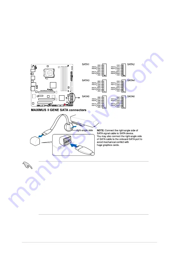
2.  ICH10R Serial ATA connectors (7-pin SATA 1-6 [blue])

These connectors are for the Serial ATA signal cables for Serial ATA hard disk 

drives and optical disc drives.
If you installed Serial ATA hard disk drives, you can create a RAID 0, 1, 5, 

and 10 configuration with the Intel

®

 Matrix Storage Technology through the 

onboard Intel

®

 ICH10R RAID controllers.

•  These connectors are set to Standard IDE mode by default. In Standard 

IDE mode, you can connect Serial ATA boot/data hard disk drives to these 

connectors. If you intend to create a Serial ATA RAID set using these 

connectors, set the 

Configure SATA as

 item in the BIOS to [RAID]. See 

section 

3.4.� Storage Configuration

 for details. Before creating a RAID 

set, refer to section 

4.4 RAID Configuration

.

•  You must install Windows

®

 XP Service Pack 1 or later version before using 

Serial ATA hard disk drives. The Serial ATA RAID feature is available only if 

you are using Windows

®

 XP SP1 or later version.

•  When using hot-plug and NCQ, set the 

Configure SATA as

 in the BIOS to 

[AHCI]. See section 

3.4.� Storage Configuration

 for details.

ROG Maximus II GENE

2-35

Содержание Maximus II Gene

Страница 1: ...Motherboard Maximus II GENE ...

Страница 2: ...CHANTABILITY OR FITNESS FOR A PARTICULAR PURPOSE IN NO EVENT SHALL ASUS ITS DIRECTORS OFFICERS EMPLOYEES OR AGENTS BE LIABLE FOR ANY INDIRECT SPECIAL INCIDENTAL OR CONSEQUENTIAL DAMAGES INCLUDING DAMAGES FOR LOSS OF PROFITS LOSS OF BUSINESS LOSS OF USE OR DATA INTERRUPTION OF BUSINESS AND THE LIKE EVEN IF ASUS HAS BEEN ADVISED OF THE POSSIBILITY OF SUCH DAMAGES ARISING FROM ANY DEFECT OR ERROR IN ...

Страница 3: ... 2 Motherboard overview 2 6 2 2 1 Motherboard layout 2 6 2 2 2 Layout contents 2 7 2 2 3 Placement direction 2 8 2 2 4 Screw holes 2 8 2 3 Central Processing Unit CPU 2 9 2 3 1 Installing the CPU 2 10 2 3 2 Installing the CPU heatsink and fan 2 13 2 3 3 Uninstalling the CPU heatsink and fan 2 14 2 4 System memory 2 15 2 4 1 Overview 2 15 2 4 2 Memory configurations 2 16 2 4 3 Installing a DIMM 2 2...

Страница 4: ...etup 3 1 Managing and updating your BIOS 3 1 3 1 1 ASUS Update utility 3 1 3 1 2 ASUS EZ Flash 2 utility 3 4 3 1 3 ASUS CrashFree BIOS 3 utility 3 5 3 2 BIOS setup program 3 6 3 2 1 BIOS menu screen 3 7 3 2 2 Menu bar 3 7 3 2 3 Navigation keys 3 7 3 2 4 Menu items 3 8 3 2 5 Submenu items 3 8 3 2 6 Configuration fields 3 8 3 2 7 Pop up window 3 8 3 2 8 Scroll bar 3 8 3 2 9 General help 3 8 3 3 Extr...

Страница 5: ...nation Voltage Auto 3 14 3 3 24 DRAM Voltage Auto 3 14 3 3 25 Nroth Bridge 1 1 Voltage Auto 3 14 3 3 26 South Bridge 1 1 Voltage Auto 3 15 3 3 27 South Bridge 1 5 Voltage Auto 3 15 3 3 28 CPU GTL Voltage Reference 0 2 Auto 3 15 3 3 29 CPU GTL Voltage Reference 1 3 Auto 3 15 3 3 30 NB GTL Reference Auto 3 15 3 3 31 DDR2 ChA B Reference Voltage Auto 3 15 3 3 32 North Bridge DDR Reference Auto 3 15 3...

Страница 6: ... 31 3 6 5 APM Configuration 3 32 3 6 4 ACPI APIC Support Enabled 3 32 3 6 6 Hardware Monitor 3 34 3 7 Boot menu 3 37 3 7 1 Boot Device Priority 3 37 3 7 2 Boot Settings Configuration 3 38 3 7 3 Security 3 39 3 8 Tools menu 3 41 3 8 1 ASUS EZ Flash 2 3 41 3 8 2 ASUS O C Profile 3 42 3 8 3 TweakIt Batch File 3 43 3 8 4 AI NET 2 3 44 3 9 Exit menu 3 45 Chapter 4 Software support 4 1 Installing an ope...

Страница 7: ...2 4 4 2 Installing Serial ATA hard disks 4 33 4 4 3 Setting the RAID item in BIOS 4 33 4 4 4 Intel Matrix Storage Manager option ROM utility 4 34 4 5 Creating a RAID driver disk 4 39 4 5 1 Creating a RAID driver disk without entering the OS 4 39 4 5 2 Creating a RAID driver disk in Windows 4 39 Chapter 5 Multiple GPU technology support 5 1 ATI CrossFireX technology 5 1 5 1 1 Requirements 5 1 5 1 2...

Страница 8: ...d on the user is encouraged to try to correct the interference by one or more of the following measures Reorient or relocate the receiving antenna Increase the separation between the equipment and receiver Connect the equipment to an outlet on a circuit different from that to which the receiver is connected Consult the dealer or an experienced radio TV technician for help Canadian Department of Co...

Страница 9: ...fore installing the motherboard and adding devices on it carefully read all the manuals that came with the package Before using the product ensure all cables are correctly connected and the power cables are not damaged If you detect any damage contact your dealer immediately To avoid short circuits keep paper clips screws and staples away from connectors slots sockets and circuitry Avoid dust humi...

Страница 10: ...r 1 Product introduction This chapter describes the features of the motherboard and the new technology it supports Chapter 2 Hardware information This chapter lists the hardware setup procedures that you have to perform when installing system components It includes description of the switches jumpers and connectors on the motherboard Chapter 3 BIOS setup This chapter tells how to change system set...

Страница 11: ...mbols used throughout this manual Typography Bold text Indicates a menu or an item to select Italics Used to emphasize a word or a phrase Key Keys enclosed in the less than and greater than sign means that you must press the enclosed key Example Enter means that you must press the Enter or Return key Key1 Key2 Key3 If you must press two or more keys simultaneously the key names are linked with a p...

Страница 12: ...fied Vendors Lists Expansion Slots 2 x PCIe2 0 x16 slots single max 16 dual x8 speed 1 x PCIe x1 slot 1 x PCI 2 2 slot Multi GPU Technology Support ATI CrossFireX Technology Storage ICH10R Southbridge 6 x SATA 3 0 Gb s ports Intel Matrix Storage Technology supports RAID 0 1 5 and 10 JMicron 363 controller 1 x UltraDMA 133 100 66 33 for up to 2 PATA devices 1 x SATA 3 0 Gb s port 1 x External SATA ...

Страница 13: ...arameter Recall Other Special Features External LCD Poster MemOK One DIMM latch Onboard Switches Power Reset MemOK Clr CMOS at rear Q Fan Plus ASUS EPU 6 Engine ASUS Q Connector ASUS Fan Xpert ASUS EZ Flash 2 ASUS CrashFree BIOS 3 ASUS MyLogo3 BIOS Features 16Mb AMI BIOS PnP DMI2 0 WfM2 0 SM BIOS 2 4 ACPI2 0a Multi Language BIOS Manageability WOL by PME WOR by PME PXE Back Panel I O Ports 1 x PS 2...

Страница 14: ...UT connector 24 pin ATX Power connector 8 pin ATX 12V Power connector 1 x En Dis able Clr CMOS header 1 x Front panel audio connector 1 x CD audio in System panel connector Software Support DVD Drivers and applications Sound Blaster X Fi Utility Futuremark 3DMark 06 Advanced Edition Kaspersky Anti Virus ASUS TurboV utility ASUS PC Probe II ASUS Update ASUS AI Suite Form Factor microATX 9 6 x 9 6 2...

Страница 15: ...1 Chapter 1 Product introduction This chapter describes the motherboard features and the new technologies it supports ...

Страница 16: ...ROG Maximus II GENE Chapter summary 1 1 1 Welcome 1 1 1 2 Package contents 1 1 1 3 Special features 1 2 ...

Страница 17: ...evices on it check the items in your package with the list below If any of the above items is damaged or missing contact your retailer 1 2 Package contents Check your motherboard package for the following items Motherboard ROG Maximus II GENE Cables 1 x Ultra DMA 133 100 66 cable 2 x Serial ATA signal cables Accessories 1 x External LCD Poster 1 x 2 in 1 ASUS Q Connector Kit 1 x I O Shield 1 x Cab...

Страница 18: ...test Intel Core 2 Extreme Core 2 Quad Core 2 Duo processors in the LGA775 package It is excellent for multi tasking multi media and enthusiastic gamers with 1600 1333 1066 800 MHz FSB The Intel Core 2 series processor is one of the most powerful CPUs in the world This motherboard also supports Intel CPUs in the new 45nm manufacturing process See page 2 9 for details Intel P45 Chipset The Intel P45...

Страница 19: ...ll disposal of the motherboard at any stage This design allows advanced user control and management to be processed at a hardware level iROG greatly increases fun during overclocking for PC enthusiasts and it provides system maintenance and management with more control and efficiency CPU Level Up A simple click for instant upgrade Ever wish that you could have a more expansive CPU Upgrade your CPU...

Страница 20: ...o increase chipset voltages without the worries of overheating It can also be used to monitor and save an overheating GPU The COP EX allows more freedom and less constraint for maximum performance achievement Loadline Calibration Optimal power boost for extreme CPU overclocking Maintaining ample voltage support for the CPU is critical during overclocking The Loadline calibration ensures stable and...

Страница 21: ...rature and adjusts fan speed accordingly to achieve quiet and efficient cooling 1 3 4 ASUS special features ASUS Power Saving Solution ASUS Power Saving solution intelligently and automatically provides balanced computing power and energy consumption ASUS EPU 6 Engine System Level Energy Saving The new ASUS EPU the world s first power saving engine has been upgraded to a new 6 engine version which...

Страница 22: ...nd update BIOS using a USB flash disk without entering the OS You can update your BIOS in a few clicks without preparing an additional floppy diskette or using an OS based flash utility See page 3 4 for details Kaspersky Anti Virus The best protection from viruses and spyware Kaspersky Anti Virus Personal offers premium antivirus protection for individual users and home offices It is based on adva...

Страница 23: ...ter 2 Hardware information This chapter lists the hardware setup procedures that you have to perform when installing system components It includes description of the jumpers and connectors on the motherboard ...

Страница 24: ...efore you proceed 2 1 2 2 Motherboard overview 2 6 2 3 Central Processing Unit CPU 2 9 2 4 System memory 2 15 2 5 Expansion slots 2 25 2 6 Jumper 2 29 2 7 Connectors 2 30 2 8 Starting up for the first time 2 47 2 9 Turning off the computer 2 48 ...

Страница 25: ...ase before handling components to avoid damaging them due to static electricity Hold components by the edges to avoid touching the ICs on them Whenever you uninstall any component place it on a grounded antistatic pad or in the bag that came with the component Before you install or remove any component ensure that the ATX power supply is switched off or the power cord is detached from the power su...

Страница 26: ...ut voltage adjustment refer to 3 3 Extreme Tweaker menu 1 CPU LED The CPU LED has two voltage displays CPU Voltage and CPU PLL Voltage you can select the voltage to display in BIOS Refer to the illustration below for the location of the CPU LED and the table below for LED definition Normal green High yellow Crazy red CPU Voltage 0 85000 1 5000 1 50625 1 69375 1 70000 2 40000 CPU PLL Voltage 1 5132...

Страница 27: ...an select the voltage to display in BIOS Refer to the illustration below for the location of the northbridge southbridge LEDs and the table below for LED definition Normal green High yellow Crazy red NB Voltage 1 10000 1 59025 1 60350 1 84200 1 85525 2 05400 FSB VTT 1 10000 1 40475 1 41800 1 60350 1 61675 2 00100 SB 1 1 Voltage 1 11341 1 60366 1 61691 1 85541 1 86866 2 00116 SB 1 5 Voltage 1 51106...

Страница 28: ...t light up when there is no hard disk drive connected to the motherboard or when the hard disk drive does not function 3 Memory LED Refer to the illustration below for the location of the memory LED and the table below for LED definition Normal green High yellow Crazy red DRAM Bus Voltage 1 80000 1 99875 2 01200 2 60825 2 62150 3 40325 2 4 Chapter 2 Hardware information ...

Страница 29: ...gging in any motherboard component The illustration below shows the location of the onboard power on switch When you turn on the ATX power supply the Power LED flashes three times to indicate that the system is ready to boot Wait till the flash stops before you press the power on switch 6 MemOK LED The MemOK LED blinks while the system is loading failsafe settings for memory compatibility after pr...

Страница 30: ...2 2 Motherboard overview 2 2 1 Motherboard layout 2 6 Chapter 2 Hardware information ...

Страница 31: ...CLRTC_SW 2 29 9 JMicron JMB363 Serial ATA connector 7 pin SATA_E1 black 2 36 10 System panel connector 20 8 pin PANEL 2 42 11 Reset switch 2 44 12 Power on switch 2 44 13 USB connectors 10 1 pin USB78 USB910 USB1112 2 36 14 Thermal sensor cable connectors 2 pin OPT_TEMP1 2 2 40 15 Digital audio connector 4 1 pin SPDIF_OUT 2 37 16 IEEE 1394a port connector 10 1 pin IE1394_2 2 37 17 Optical drive au...

Страница 32: ...e it into the chassis in the correct orientation The edge with external ports goes to the rear part of the chassis as indicated in the image below 2 2 4 Screw holes Place eight 8 screws into the holes indicated by circles to secure the motherboard to the chassis Place this side towards the rear of the chassis 2 8 Chapter 2 Hardware information ...

Страница 33: ...nts ASUS will shoulder the cost of repair only if the damage is shipment transit related Keep the cap after installing the motherboard ASUS will process Return Merchandise Authorization RMA requests only if the motherboard comes with the cap on the LGA775 socket The product warranty does not cover damage to the socket contacts resulting from incorrect CPU installation removal or misplacement loss ...

Страница 34: ...e PnP cap unless you are installing a CPU 2 Press the load lever with your thumb A then move it to the left B until it is released from the retention tab A B Load lever Retention tab 3 Lift the load lever in the direction of the arrow to a 135º angle 4 Lift the load plate with your thumb and forefinger to a 100º angle 4A then push the PnP cap from the load plate window to remove 4B Load plate PnP ...

Страница 35: ...hat it is spread in an even thin layer Some heatsinks come with pre applied thermal interface material If so skip this step The CPU fits in only one correct orientation DO NOT force the CPU into the socket to prevent bending the connectors on the socket and damaging the CPU The thermal interface material is toxic and inedible If it gets into your eyes or touches your skin ensure to wash it off imm...

Страница 36: ... Technology EM64T Enhanced Intel SpeedStep Technology EIST and Hyper Threading Technology Refer to the Appendix for more information on these CPU features 7 Close the load plate A then push the load lever B until it snaps into the retention tab A B 2 12 Chapter 2 Hardware information ...

Страница 37: ... installed the motherboard to the chassis before you install the CPU fan and heatsink assembly Orient the heatsink and fan assembly such that the CPU fan cable is closest to the CPU fan connector To install the CPU heatsink and fan 1 Place the heatsink on top of the installed CPU ensuring that the four fasteners match the holes on the motherboard 2 Push down two fasteners at a time in a diagonal s...

Страница 38: ...ng the CPU heatsink and fan To uninstall the CPU heatsink and fan 1 Disconnect the CPU fan cable from the connector on the motherboard 2 Rotate each fastener counterclockwise 3 Pull up two fasteners at a time in a diagonal sequence to disengage the heatsink and fan assembly from the motherboard A A B B A A B B 4 Carefully remove the heatsink and fan assembly from the motherboard 2 14 Chapter 2 Har...

Страница 39: ...imensions as a DDR DIMM but is notched differently to prevent installation on a DDR DIMM socket The figure illustrates the location of the DDR2 DIMM sockets Recommended memory configurations One DIMM You may install one memory module in any slot as a single channel operation Two DIMMs dual channel operation Four DIMMs dual channel operation ROG Maximus II GENE 2 15 ...

Страница 40: ...memory sizes in Channel A and Channel B The system maps the total size of the lower sized channel for the dual channel configuration Any excess memory from the higher sized channel is then mapped for single channel operation Always install DIMMs with the same CAS latency For optimum compatibility we recommend that you obtain memory modules from the same vendor Due to the memory address limitation ...

Страница 41: ...upport Optional A B C Apacer BoxP N CH 02GAF C0KK2 78 0AG9S 9KF 2048MB Kit of 2 DS N A Heat Sink Package 5 5 5 15 Apacer BoxP N CH 04GAF F0KK2 78 AAGAL 9KF 4096MB Kit of 2 DS N A Heat Sink Package 5 5 5 15 CORSAIR BoxP N TWIN2X4096 8500C5DF CM2X2048 8500C5D EPP 4096MB Kit of 2 DS N A Heat Sink Package 5 5 5 15 2 1 Crucial BL12864AA106A 8FE5 EPP 1024MB SS N A Heat Sink Package 5 5 5 15 2 0 G SKILL ...

Страница 42: ...2 2 KINGSTON KHX8500D2K2 2GN EPP 2048MB Kit of 2 DS N A Heat Sink Package 2 2 MICRON MT8HTF12864AY 1GAE1 1024MB SS MICRON D9JKH 7 MICRON MT16HTF25664AY 1GAE1 2048MB DS MICRON D9JKH 7 OCZ OCZ2N10662GK EPP 2048MB Kit of 2 DS Heat Sink Package OCZ OCZ2N1066SR2GK EPP 2048MB Kit of 2 DS N A Heat Sink Package 5 2 10 OCZ OCZ2RPR10664GK 4096MB Kit of 2 DS N A Heat Sink Package 5 2 2 Transcend TX1066QLU 2G...

Страница 43: ...kage 4 2 0 2 1 G SKILL F2 6400CL5D 4GBPQ 4096MB Kit of 2 DS N A Heat Sink Package 5 1 8 1 9 G SKILL F2 6400CL6D 4GBMQ 4096MB Kit of 2 DS N A Heat Sink Package 6 1 8 1 9 G SKILL F2 6400CL6D 8GBMQ 8192MB Kit of 2 DS N A Heat Sink Package 6 6 6 18 1 8 GEIL GB22GB6400C4DC 2048MB Kit of 2 DS GEIL GL2L64M088BA30EB 4 4 4 12 2 0 GEIL GB22GB6400C5DC 2048MB Kit of 2 DS GEIL GL2L64M088BA30EB 5 5 5 15 1 8 GEI...

Страница 44: ...B DS ELPIDA E2108ABSE 8G E NANYA NT 512T64U88B0BY 25C 512MB SS NT5TU64M8BE 25C 5 NANYA NT1GT64U8HB0BY 25C 1024MB DS NT5TU64M8BE 25C 5 NANYA NT1GT64U8HCOBY 25D 1024MB DS NANYA NT5TU64M8CE 25D NANYA NT2GT64U8HC0BY AC 2048MB DS NANYA NT5TU128M8CE AC 5 OCZ OCZ2G8001G 1024MB DS N A Heat Sink Package 5 1 8 OCZ OCZ2G8002GK 1024MB DS Heat Sink Package 5 OCZ OCZ2T8002GK EPP 1024MB DS N A Heat Sink Package ...

Страница 45: ... DS Elixir N2TU 51280BE 25C 5 1 8 Elixir M2Y2G64TU8HD4B AC 2048MB DS Elixir N2TU1G80DE AC 5 Kingbox N A 2048MB DS Kingbox EPD2128082200E 3 800 5 5 5 15 Kingbox N A 2048MB DS MICRON D9HNL Kingbox N A 2048MB DS KINGBOX EPD2128082200E 3 Mushkin XP2 6400 1024MB SS Heat Sink Package 4 Oci 04701G16CZ5D2A 1024MB DS Jnfinity 64M8PC6400 5 Patriot PSD2 51280081 512MB SS PATRIOT PM64M8D2BU 25EC Patriot PSD22...

Страница 46: ... KVR667 D2N5 1G 1024MB DS ELPIDA E5108AJBG 6E E 667 5 5 5 15 1 8 KINGSTON KVR667D2E5 1G 1024MB DS ELPIDA E5108AGBG 6E E ECC 1 8 KINGSTON KVR667D2E5 2G 2048MB DS MICRON D9HNL ECC 1 8 KINGSTON KVR667D2N5 2G 2048MB DS KINGSTON D1288TPFCGL25U 667 5 5 5 15 1 8 NANYA NT 512T64U88B0BY 3C 512MB SS NANYA NT5TU64M8BE 3C 5 1 8 NANYA NT2GT64U8HB0JY 3C 2048MB DS NT5TU128M8BJ 3C 5 OCZ OCZ26671024V 1024MB SS Ram...

Страница 47: ...bility Visit the ASUS website at www asus com for the latest QVL SS Single sided DS Double sided DIMM support A Supports one module inserted in any slot as single channel memory configuration B Supports one pair of modules inserted into either the yellow slots or the black slots as one pair of dual channel memory configuration C Supports four modules inserted into both the yellow and black slots a...

Страница 48: ...lace and the DIMM is properly seated Ensure to unplug the power supply before adding or removing DIMMs or other system components Failure to do so may cause severe damage to both the motherboard and the components A DIMM is keyed with a notch so that it fits in only one direction DO NOT force a DIMM into a socket to avoid damaging the DIMM Unlocked retaining clip DIMM notch 1 Unlock a DIMM socket ...

Страница 49: ...s with the screw you removed earlier 6 Replace the system cover 2 5 2 Configuring an expansion card After installing the expansion card configure it by adjusting the software settings 1 Turn on the system and change the necessary BIOS settings if any See Chapter 3 for information on BIOS setup 2 Assign an IRQ to the card Refer to the tables on the next page 3 Install the software drivers for the e...

Страница 50: ...CI Steering 11 6 IRQ Holder for PCI Steering 12 7 Reserved 13 8 Numeric Data Processor 14 9 Primary IDE Channel ICH A B C D E F G H PCIE1_1 shared LAN shared PCI_1 shared USB controller 1 shared USB controller 2 shared USB controller 3 shared USB controller 4 shared USB controller 5 shared USB controller 6 shared USB 2 0 controller 1 shared USB 2 0 controller 2 shared SATA controller 1 shared SATA...

Страница 51: ...ards and other cards that comply with the PCI Express specifications Install a PCIe x1 device to a PCIe x1 slot prior to a PCIe x16 slot 2 5 6 PCI Express 2 0 x16 slots This motherboard has two PCI Express 2 0 x16 slots that support PCI Express x16 2 0 graphic cards complying with the PCI Express specifications Refer to the figure below for the location of the slots PCI Express 2 0 x16_1 slot PCI ...

Страница 52: ...x16_2 blue slots for PCI Express x16 graphics cards to get better performance We recommend that you provide sufficient power when running CrossFireX mode See page 2 41 for details Connect a chassis fan to the motherboard connector labeled CHA_FAN1 2 when using multiple graphics cards for better thermal environment See page 2 39 for details 2 28 Chapter 2 Hardware information ...

Страница 53: ...ithout 5VSB power AC power loss S5 Power off with 5VSB power The system shuts dowm immediately The clr CMOS switch will not function if the CLRTC_SW jumper is moved to the Disable position but the shutdwon function in S0 mode DOS mode still works Ensure to re enter your previous BIOS settings after you clear the CMOS You do not need to clear the RTC when the system hangs due to CPU overclocking Wi...

Страница 54: ...3 and 4 7 External SATA port 3 LAN RJ 45 port 8 Optical S PDIF Out port 4 USB 2 0 ports 5 and 6 9 USB 2 0 ports 1 and 2 5 Clear CMOS switch 10 Audio I O ports To use hot plug set the Controller Mode in the BIOS settings to AHCI mode See section 3 5 3 Onboard Devices Configuration for details 2 30 Chapter 2 Hardware information ...

Страница 55: ...ts Connect to Headphone and Mic Audio 2 4 6 or 8 channel configuration Port Headset 2 channel 4 channel 6 channel 8 channel Light Blue Line In Line In Line In Line In Lime Line Out Front Speaker Out Front Speaker Out Front Speaker Out Pink Mic In Mic In Mic In Mic In Orange Center Subwoofer Center Subwoofer Black Rear Speaker Out Rear Speaker Out Rear Speaker Out Gray Side Speaker Out Speed LED Ac...

Страница 56: ...Connect to Stereo Speakers Connect to 2 1 channel Speakers Connect to 4 1 channel Speakers 2 32 Chapter 2 Hardware information ...

Страница 57: ...Connect to 5 1 channel Speakers Connect to 7 1 channel Speakers ROG Maximus II GENE 2 33 ...

Страница 58: ...rive jumper setting Mode of device s Cable connector Single device Cable Select or Master Black Two devices Cable Select Master Black Slave Gray Master Master Black or gray Slave Slave Pin 20 on the IDE connector is removed to match the covered hole on the Ultra DMA cable connector This prevents incorrect insertion when you connect the IDE cable Use the 80 conductor IDE cable for Ultra DMA 133 100...

Страница 59: ...erial ATA boot data hard disk drives to these connectors If you intend to create a Serial ATA RAID set using these connectors set the Configure SATA as item in the BIOS to RAID See section 3 4 5 Storage Configuration for details Before creating a RAID set refer to section 4 4 RAID Configuration You must install Windows XP Service Pack 1 or later version before using Serial ATA hard disk drives The...

Страница 60: ...ectors Doing so will damage the motherboard You can connect the USB cable to ASUS Q Connector USB blue first and then install the Q Connector USB to the USB connector onboard 3 JMicron JMB363 Serial ATA connector 7 pin SATA_E1 black This connector is for a Serial ATA signal cable for an external Serial ATA hard disk drive To enable hot plugging set the Controller Mode item in the BIOS setting to A...

Страница 61: ... cable to the IEEE 1394a connector Doing so will damage the motherboard 6 Digital audio connector 4 1 pin SPDIF_OUT This connector is for an additional Sony Philips Digital Interface S PDIF port s Connect the S PDIF Out module cable to this connector then install the module to a slot opening at the back of the system chassis The S PDIF module is purchased separately The IEEE 1394a cable is purchas...

Страница 62: ...r to avail of the motherboard s high definition audio capability If you want to connect a high definition front panel audio module to this connector set the Front Panel Type item in the BIOS setup to HD Audio if you want to connect an AC 97 front panel audio module to this connector set the item to AC97 By default this connector is set to HD Audio 7 Optical drive audio connector 4 pin CD These con...

Страница 63: ...ng that the black wire of each cable matches the ground pin of the connector DO NOT forget to connect the fan cables to the fan connectors Insufficient air flow inside the system may damage the motherboard components These are not jumpers DO NOT place jumper caps on the fan connectors If you install two VGA cards we recommend that you plug the chassis fan cable to the motherboard connector labeled...

Страница 64: ... other ends to the devices which you want to monitor temperature The optional fan1 2 can work with the temperature sensors for a better cooling effect Enable OPT FAN1 2 overheat protection in BIOS if you connect thermal sensor cables to these connectors Refer to page 3 34 for details The thermal sensor cable is purchased separately 2 40 Chapter 2 Hardware information ...

Страница 65: ...orget to connect the 8 pin EATX12 V power plug otherwise the system will not boot Use of a PSU with a higher power output is recommended when configuring a system with more power consuming devices The system may become unstable or may not boot up if the power is inadequate If you are uncertain about the minimum power supply requirement for your system refer to the Recommended Power Supply Wattage ...

Страница 66: ...4 pin connector is for the chassis mounted system warning speaker The speaker allows you to hear system beeps and warnings ATX power button soft off button 2 pin PWRSW This connector is for the system power button Pressing the power button turns the system on or puts the system in sleep or soft off mode depending on the BIOS settings Pressing the power switch for more than four seconds while the s...

Страница 67: ...s and then match them to their respective front panel cable labels The labels on the front panel cables may vary depending on the chassis model 2 Install the ASUS Q Connector to the system panel connector ensuring the orientation matches the labels on the motherboard 3 The front panel functions are now enabled The figure shows the Q Connector is properly installed on the motherboard IDE_LED POWER ...

Страница 68: ...bare or open case system This is ideal for overclockers and gamers who continually change settings to enhance system performance 1 Power on switch Press the power on switch to wake power up the system 2 Reset switch Press the reset switch to reboot the system 2 44 Chapter 2 Hardware information ...

Страница 69: ...3 MemOK switch Press the MemOK switch to load failsafe settings for memory compatibility and improving system boot success ROG Maximus II GENE 2 45 ...

Страница 70: ...eld openings 1 Install the I O shield to the chassis by snapping it in place from inside 3 Thread the LCD Poster cable through the back I O shield opening until the stopper fits the opening 4 Locate and connect the LCD Poster cable to the LCD_CON connector 5 Place the LCD Poster on the chassis or to wherever you like 2 46 Chapter 2 Hardware information ...

Страница 71: ...r LED may light up or switch between orange and green after the system LED turns on The system then runs the power on self tests or POST While the tests are running the BIOS beeps see BIOS beep codes table below or additional messages appear on the screen If you do not see anything within 30 seconds from the time you turned on the power the system may have failed a power on test Check the jumper s...

Страница 72: ... button to shut down the computer 3 The power supply should turn off after Windows shuts down 2 9 2 Using the dual function power switch While the system is ON pressing the power switch for less than four seconds puts the system to sleep mode or to soft off mode depending on the BIOS setting Pressing the power switch for more than four seconds lets the system enter the soft off mode regardless of ...

Страница 73: ...3 BIOS setup This chapter tells how to change the system settings through the BIOS Setup menus Detailed descriptions of the BIOS parameters are also provided ...

Страница 74: ...mus II GENE 3 1 Managing and updating your BIOS 3 1 3 2 BIOS setup program 3 6 3 3 Extreme Tweaker menu 3 9 3 4 Main menu 3 17 3 5 Advanced menu 3 23 3 6 Power menu 3 31 3 7 Boot menu 3 37 3 8 Tools menu 3 41 3 9 Exit menu 3 45 ...

Страница 75: ...al motherboard BIOS using the ASUS Update utility Installing ASUS Update To install ASUS Update 1 Place the support DVD in the optical drive The Drivers menu appears 2 Click the Utilities tab then click Install ASUS Update VX XX XX 3 The ASUS Update utility is copied to your system 3 1 1 ASUS Update utility The ASUS Update is a utility that allows you to manage save and update the motherboard BIOS...

Страница 76: ...rk traffic or click Auto Select Click Next Updating the BIOS through the Internet To update the BIOS through the Internet 1 Launch the ASUS Update utility from the Windows desktop by clicking Start Programs ASUS ASUSUpdate ASUSUpdate The ASUS Update main window appears 2 Select Update BIOS from the Internet option from the drop down menu then click Next ...

Страница 77: ...om a file option from the drop down menu then click Next 4 From the FTP site select the BIOS version that you wish to download Click Next 5 Follow the screen instructions to complete the update process The ASUS Update utility is capable of updating itself through the Internet Always update the utility to avail all its features 3 Locate the BIOS file from the Open window then click Open 4 Follow th...

Страница 78: ...sh 2 and press Enter to enable it ASUSTek EZ Flash 2 BIOS ROM Utility V3 34 Current ROM Update ROM A Note Enter Select or Load Tab Switch V Drive Info Up Down Home End Move B Backup Esc Exit FLASH TYPE MXIC 25L1605A PATH A BOARD RampageII GENE VER 0205 DATE 01 13 2009 BOARD Unknown VER Unknown DATE Unknown 2 Press Tab to switch between drives until the correct BIOS file is found When found EZ Flas...

Страница 79: ... and save it to a USB flash drive Recovering the BIOS To recover the BIOS 1 Turn on the system 2 Insert the motherboard support DVD to the optical drive or the USB flash drive containing the BIOS file to the USB port 3 The utility automatically checks the devices for the BIOS file When found the utility reads the BIOS file and starts flashing the corrupted BIOS file 4 Turn off the system after the...

Страница 80: ...ram Press Del during the Power On Self Test POST to enter the Setup utility otherwise POST continues with its test routines If you wish to enter Setup after POST restart the system by pressing Ctrl Alt Delete or by pressing the reset button on the system chassis You can also restart by turning the system off and then back on Do this last option only if the first two failed The Setup program is des...

Страница 81: ...ight corner of a menu screen are the navigation keys for that particular menu Use the navigation keys to select items in the menu and change the settings 3 2 1 BIOS menu screen Some of the navigation keys differ from one screen to another v02 61 C Copyright 1985 2009 American Megatrends Inc BIOS SETUP UTILITY Extreme Tweaker Main Advanced Power Boot Tools Exit Use ENTER TAB or SHIFT TAB to select ...

Страница 82: ...it then press Enter to display a list of options Refer to 3 2 7 Pop up window 3 2 7 Pop up window Select a menu item then press Enter to display a pop up window with the configuration options for that item 3 2 8 Scroll bar A scroll bar appears on the right side of a menu screen when there are items that do not fit on the screen Press the Up Down arrow keys or Page Up Page Down keys to display the ...

Страница 83: ...RAM CLK Skew on Channel B2 Auto DRAM Timing Control Auto 1st Information 5 5 5 15 3 36 5 3 2nd Information 8 3 5 4 6 4 7 3rd Information 13 5 1 5 5 DRAM Static Read Control Auto v02 61 C Copyright 1985 2009 American Megatrends Inc Select Screen Select Item Change Option F1 General Help F10 Save and Exit ESC Exit DRAM Read Training Auto MEM OC Charger Auto Ai Clock Twister Auto Ai Transaction Boost...

Страница 84: ...verclocking parameters Auto Loads the standard settings for the system CPU Level Up Allows you to select a CPU level and the related parameters will be adjusted automatically 3 3 4 CPU Ratio Setting Auto Allows you to adjust the ratio between CPU Core Clock and FSB Frequency Use the and keys to adjust the value The valid value ranges differently according to your CPU model 3 3 5 CPU Configuration ...

Страница 85: ...annel A B 1 2 Auto Adjusting these items may help enhancing DRAM overclocking ability Configuration options Auto Advance 350ps Advance 300ps Advance 250ps Advance 200ps Advance 150ps Advance 100ps Advance 50ps Normal Delay 50ps Delay 100ps Delay 150ps Delay 200ps Delay 250ps Delay 300ps Delay 350ps 3 3 12 DRAM Timing Control Auto Configuration options Auto Manual The following sub items apprear on...

Страница 86: ...D to WRITE Delay S D Auto Configuration options Auto 1 DRAM Clocks 15 DRAM Clocks Write to Read to Delay S Auto Configuration options Auto 1 DRAM Clocks 15 DRAM Clocks WRITE to READ Delay D Auto Configuration options Auto 1 DRAM Clocks 15 DRAM Clocks READ to READ Delay S Auto Configuration options Auto 1 DRAM Clocks 15 DRAM Clocks READ to READ Delay D Auto Configuration options Auto 1 DRAM Clocks ...

Страница 87: ...this function 3 3 16 Ai Clock Twister Auto Allows you to configure the DRAM performance Auto BIOS automatically adjusts the DRAM performance Moderate Maintains the normal DRAM performance Light Enhances the DRAM compatibility Lighter Better enhances the DRAM compatibility Strong Enhances the DRAM performance Stronger Better enhances the DRAM performance 3 3 17 Ai Transaction Booster Auto Allows yo...

Страница 88: ...3 20 PCIE Frequency 100 Allows you to set the PCI Express frequency Use the and keys to adjust the PCIE frequency You can also type in the desired value using the numeric keypad The values range from 100 to 180 This item appears when you set Ai Overclock Tuner to Manual 3 3 21 CPU Voltage Auto Allows you to set the CPU VCore voltage Refer to the CPU documentation before setting the CPU Vcore volta...

Страница 89: ...ferent ratio might enhance CPU overclocking ability Configuration options Auto 0 67x 0 61x 3 3 31 DDR2 ChA B Reference Voltage Auto Allows you to set the DDR2 ChA and ChB reference voltage or your can set to Auto for the safe mode Different ratio might enhance CPU overclocking ability 3 3 32 North Bridge DDR Reference Auto Allows you to set the North Bridge DDR reference voltage or your can set to...

Страница 90: ...3 16 Chapter 3 BIOS setup 3 3 36 PCIE Spread Spectrum Auto Disabled Enhances the PCIE overclocking ability Auto Set to Auto for EMI control ...

Страница 91: ...Refer to section 3 2 1 BIOS menu screen for information on the menu screen items and how to navigate through them v02 61 C Copyright 1985 2009 American Megatrends Inc BIOS SETUP UTILITY Extreme Tweaker Main Advanced Power Boot Tools Exit Use ENTER TAB or SHIFT TAB to select a field Use or to configure system Time Select Screen Select Item Change Field Tab Select Field F1 General Help F10 Save and ...

Страница 92: ...fically configuring a CD ROM drive ARMD Select ARMD ATAPI Removable Media Device if your device is either a ZIP LS 120 or MO drive LBA Large Mode Auto Enables or disables the LBA Logical Block Addressing mode Auto Select Auto to enable the LBA mode Logical Block Addressing mode if the device supports this mode and if the device was not previously formatted with LBA mode disabled Disabled Disable t...

Страница 93: ...ardware devices installed with much less CPU overhead The DMA mode consists of SDMA single word DMA MDMA multi word DMA and UDMA Ultra DMA Setting to Auto allows automatic selection of the DMA mode or you can select from the following options SWDMA1 SWDMA2 MWDMA0 MWDMA1 MWDMA2 UDMA0 UDMA1 UDMA2 UDMA3 UDMA4 UDMA5 SMART Monitoring Auto Auto Allows automatic selection of the S M A R T Smart Monitorin...

Страница 94: ...om workloads by allowing the drive to internally optimize the order of commands Hard Disk Write Protect Disabled Enabled Enable device write protection This function will be effective only if the device is accessed through BIOS Disabled Disable this function SATA Detect Time Out Sec 35 Selects the time out value for detecting ATA ATAPI devices from the following options 0 5 10 15 20 25 30 35 3 4 5...

Страница 95: ...or AHCI configuration It appears only when you set the Configure SATA as item under SATA Configuration to AHCI AHCI CD DVD Boot Time out 15 Selects the boot time out value for SATA CD DVD devices in AHCI mode from the following options 0 5 10 15 20 25 30 35 AHCI Port1 6 XXXX Displays the status of auto detection of SATA devices BIOS SETUP UTILITY Main AHCI Settings AHCI CD DVD Boot Time out 15 AHC...

Страница 96: ...lly detects the items in this menu v02 61 C Copyright 1985 2009 American Megatrends Inc BIOS SETUP UTILITY Main Select Screen Select Item Change Field F1 General Help F10 Save and Exit ESC Exit BIOS Information Version 0218 Build Date 03 19 09 Processor Type Intel R Pentium R D CPU 000 2 67GHz Speed 2133MHz System Memory Usable Size 1024MB ...

Страница 97: ...IPnP LCD Poster and LED Control iROG Configuration v02 61 C Copyright 1985 2009 American Megatrends Inc BIOS SETUP UTILITY Advanced Sets the ratio between CPU Core Clock and the FSB Frequency NOTE If an invalid ratio is set in CMOS then actual and setpoint values may differ NOTE Please key in ratio numbers directly Select Screen Select Item F1 General Help F10 Save and Exit ESC Exit Configure adva...

Страница 98: ...nctions Disabled Disables this function Intel R Virtualization Tech Enabled Enabled Allows a hardware platform to run multiple operating systems separately and simultaneously enabling one system to virtually function as several systems Disabled Disables this function CPU TM function Enabled Enabled Enables the overheated CPU to throttle its clock speed to cool down Disabled Disables this function ...

Страница 99: ...his function Initiate Graphic Adapter PEG PCI Allows you to decide which graphics controller to use as the primary boot device Configuration options PCI PEG PEG PCI BIOS SETUP UTILITY Advanced Advanced Chipset Settings WARMING Setting wrong values in below sections may cause system to malfunction North Bridge Configuration BIOS SETUP UTILITY Advanced North Bridge Configuration Memory Remap Feature...

Страница 100: ...s the J Micron eSATA PATA controller Disabled Disables the controller Controller Mode IDE Allows you to set the controller mode Configuration options IDE AHCI Onboard PCIEx1 LAN Enabled Allows you to enable or disable the onboard PCIEx1 LAN controller Configuration options Enabled Disabled Onboard LAN BootROM Disabled This item appears only when you enable the previous item Enabled Enables the onb...

Страница 101: ...e to HiSpeed 480 Mbps The USB 2 0 Controller Mode item appears only when you enable the USB 2 0 Controller BIOS EHCI Hand off Enabled Enabled Enables the support for operating systems without an EHCI hand off feature Disabled Disables the function Onboard VIA 1394 Enabled Enabled Enables the VIA 1394 controller Disabled Disables the controller 3 5 4 USB Configuration The items in this menu allows ...

Страница 102: ...tect the presence of USB devices at startup If detected the USB controller legacy mode is enabled If no USB device is detected the legacy USB support is disabled Enabled Enables the support for USB devices on legacy operating systems OS Disabled Disables the function v02 61 C Copyright 1985 2009 American Megatrends Inc BIOS SETUP UTILITY Advanced NO lets the BIOS configure all the devices in the s...

Страница 103: ...ge All Temperature All Fan Speed All LED Control Enabled Allows you to enable or disable the onboard LEDs control Configuration options Enabled Disabled The following items appear only when you set All LED Control to Enabled Voltiminder LED Enabled Allows you to enable or disable the onboard Voltiminder LED Configuration options Enabled Disabled CPU LED Selection CPU Allows you to switch the onboa...

Страница 104: ...ate Allows you to set the iROG Time Keeper operation mode Configuration options Last State Disabled Enabled v02 61 C Copyright 1985 2009 American Megatrends Inc BIOS SETUP UTILITY Advanced iROG Timer Keeper System will record using time every 1 minute Select Screen Select Item F1 General Help F10 Save and Exit ESC Exit iROG Configuration iROG ID_Number Information iROG BC_Number A2 iROG_1 ID_Numbe...

Страница 105: ...S3 STR resume Disabled When set to Disabled the system will not invoke VGA BIOS POST on S3 STR resume Enabled When set to Enabled the system invokes VGA BIOS POST on S3 STR resume 3 6 3 ACPI 2 0 Support Disabled Disabled When set to Disabled the system will not add additional tables as per ACPI 2 0 specifications v02 61 C Copyright 1985 2009 American Megatrends Inc BIOS SETUP UTILITY Extreme Tweak...

Страница 106: ...grammable Interrupt Controller APIC Disabled When set to Disabled the system disable the Advanced Configuration and Power Interface ACPI support in the Advanced Programmable Interrupt Controller APIC Enabled When set to Enabled the ACPI APIC table pointer is included in the RSDT pointer list v02 61 C Copyright 1985 2009 American Megatrends Inc BIOS SETUP UTILITY Advanced Select Screen Select Item ...

Страница 107: ...rom S5 by PCI devices Disabled Disables the PME to wake up from S5 by PCI devices Enabled Allows you to turn on the system through a PCI LAN or modem card This feature requires an ATX power supply that provides at least 1A on the 5VSB lead Power On By PCIE Devices Disabled Allows you to enable or disable the PCIE devices to generate a wake event Disabled Disables the PCIE devices to generate a wak...

Страница 108: ...if you do not wish to display the detected temperatures NB overheat protection SB overheat protection 100ºC The system automatically shuts down when the northbridge or southbridge chipset is heated over the set temperature to protect it from damage Configuration optitons Disabled 70ºC 80ºC 90ºC 100ºC OPT FAN1 2 overheat protection 100ºC Allows you to set the temperature over which the system autom...

Страница 109: ...s Q Fan Control Disabled Allows you to enable or disable the Chassis fan controller Disabled Disables the Chassis Q fan controller Enabled Enables the Chassis Q fan controller The Chassis Fan Profile item appears when you enable the Chassis Fan Control feature BIOS SETUP UTILITY Power Fan Speed Control CPU Q Fan Control Disabled Chassis Q Fan Control Disabled OPTFan1 Control Disabled OPTFan2 Contr...

Страница 110: ...and OPTFan1 2 Full Speed Temp item Configuration options Disabled Duty Mode User Mode You need to connect the thermal sensor cables to the OPT_TEMP1 2 connectors to enable this function OPTFan1 2 Duty 50 Allows you to set the fan duty cycle This item appears when the OPTFan1 2 Control item is set to Duty Mode Configuration options 40 50 60 70 80 90 OPTFan1 2 Low Speed Temp 25 C Allows you to set t...

Страница 111: ...d Power Boot Tools Exit Specifies the Boot Device Priority sequence A virtual floppy disk drive Floppy Drive B may appear when you set the CD ROM drive as the first boot device Select Screen Select Item Enter Go to Sub Screen F1 General Help F10 Save and Exit ESC Exit Boot Settings Boot Device Priority Boot Settings Configuration Security v02 61 C Copyright 1985 2009 American Megatrends Inc BIOS S...

Страница 112: ... Display Mode Force BIOS Sets the display mode for option ROM Force BIOS Keep Current Bootup Num Lock On Allows you to select the power on state for the NumLock On Sets the power on state of the NumLock to On Off Sets the power on state of the NumLock to Off Wait for F1 If Error Enabled When set to Enabled the system waits for the F1 key to be pressed when error occurs Hit DEL Message Display Enab...

Страница 113: ...ting a user password To clear the supervisor password select the Change Supervisor Password then press Enter The message Password Uninstalled appears If you forget your BIOS password you can clear it by erasing the CMOS Real Time Clock RTC RAM See section 2 6 Jumper for information on how to erase the RTC RAM 3 7 3 Security The Security menu items allow you to change the system security settings S...

Страница 114: ...ess Enter 2 On the password box that appears type a password composed of at least six letters and or numbers then press Enter 3 Confirm the password when prompted The message Password Installed appears after you set your password successfully To change the user password follow the same steps as in setting a user password Password Check Setup When set to Setup BIOS checks for user password when acc...

Страница 115: ...25L1605A PATH A BOARD Maximus II GENE VER 0218 H 00 B 01 DATE 03 19 2009 BOARD Unknown VER Unknown DATE Unknown 3 8 Tools menu The Tools menu items allow you to configure options for special functions Select an item then press Enter to display the sub menu v02 61 C Copyright 1985 2009 American Megatrends Inc BIOS SETUP UTILITY Extreme Tweaker Main Advanced Power Boot Tools Exit Press ENTER to run ...

Страница 116: ...Note Enter Select or Load Tab Switch V Drive Info Up Down Home End Move B Backup Esc Exit PATH A BOARD Maximus II GENE VER 0218 DATE 03 19 2009 BOARD Unknown VER Unknown DATE Unknown Current CMOS v02 61 C Copyright 1985 2009 American Megatrends Inc BIOS SETUP UTILITY Tools Typing your profile name 0 9 a z A Z are acceptable Select Screen Select Item F1 General Help F10 Save and Exit ESC Exit O C P...

Страница 117: ... Load TweakIt Batch File to Allows you to load the desired TweakIt batch file Configuration options None File 1 File 2 FSB Frequency CPU Voltage CPU PLL Voltage FSB Termination Voltage North Bridge 1 1 Voltage South Bridge 1 1 Voltage South Bridge 1 5 Voltage DRAM Voltage Allows you to use the and keys to adjust the values for each item Refer to 3 3 Extreme Tweaker Menu for details v02 61 C Copyri...

Страница 118: ...or disables checking of the LAN cable during the Power On Self Test POST Configuration options Disabled Enabled BIOS SETUP UTILITY Tools Ai Net 2 Pair Status Length Check Realtek LAN cable Disabled Check Realtek LAN cable during POST It will take 3 to 10 seconds to diagnose LAN cable ...

Страница 119: ...want to save the changes that you made to the Setup program If you made changes to fields other than System Date System Time and Password the BIOS asks for a confirmation before exiting Discard Changes This option allows you to discard the selections you made and restore the previously saved values After selecting this option a confirmation appears Select YES to discard any changes and load the pr...

Страница 120: ...3 46 Chapter 3 BIOS setup ...

Страница 121: ...4 Software support This chapter describes the contents of the support DVD that comes with the motherboard package and the software ...

Страница 122: ...OG Maximus II GENE Chapter summary 4 4 1 Installing an operating system 4 1 4 2 Support DVD information 4 1 4 3 Software information 4 9 4 4 RAID configurations 4 32 4 5 Creating a RAID driver disk 4 49 ...

Страница 123: ...ies that you can install to avail all motherboard features 4 2 1 Running the support DVD Place the support DVD to the optical drive The DVD automatically displays the Drivers menu if Autorun is enabled in your computer Motherboard settings and hardware options vary Use the setup procedures presented in this chapter for reference only Refer to your OS documentation for detailed information Ensure t...

Страница 124: ...ation wizard Intel Chipset Inf Update Program Installs the Intel chipset inf update program Realtek RTL8111B C LAN Driver Installs the Realtek Gigabit Ethernet Driver VIA Audio Driver Installs the VIA audio driver and application Sound Blaster X Fi Installs the Sound Blaster X Fi driver and utility ASUS TweakIt Installs the ASUS TweakIt driver and utility USB 2 0 Driver Installs the USB 2 0 driver...

Страница 125: ...tallation Wizard ASUS Update The ASUS Update utility allows you to update the motherboard BIOS in Windows environment This utility requires an Internet connection either through a network or an Internet Service Provider ISP ASUS PC Probe II This smart utility monitors the fan speed CPU temperature and system voltage and alerts you of any detected problems This utility helps you keep your computer ...

Страница 126: ... virus application scans identifies and removes computer viruses View the online help for detailed information 3DMark06 Software Installs the Futuremark 3DMark06 system benchmark application Corel MediaOne Starter Installs the Corel MediaOne Starter application to easily manage edit share and protect your multimedia data ASUS TurboV Installs ASUS TurboV the advanced overclocking tool for extreme O...

Страница 127: ...ver disk JMicron JMB36X 32 64 bit RAID AHCI Driver Allows you to create a JMicron JMB36X RAID AHCI driver disk for 32 64bit system 4 2 5 Manual menu The Manuals menu contains a list of supplementary user manuals Click an item to open the folder of the user manual Most user manual files are in Portable Document Format PDF Install the Adobe Acrobat Reader from the Utilities menu before opening a use...

Страница 128: ...tab to display the ASUS contact information You can also find this information on the inside front cover of this user guide 4 2 6 Video menu Click the Video tab to display a list of video clips Click the video titles to watch ROG users outstanding performances with ROG motherboards ...

Страница 129: ...the screen give additional information on the motherboard and the contents of the support DVD Click an icon to display the specified information Motherboard Info Displays the general specifications of the motherboard Browse this DVD Displays the support DVD contents in graphical format ...

Страница 130: ...t Filelist Displays the contents of the support DVD and a brief description of each in text format Technical support form Displays the ASUS Technical Support Request Form that you have to fill out when requesting technical support ...

Страница 131: ... 3 1 1 ASUS Update utility for details 2 Select Options from the drop down menu then click Next 3 Check the option Launch MyLogo to replace system boot logo before flashing BIOS then click Next 4 Select Update BIOS from a file from the drop down menu then click Next 5 When prompted locate the new BIOS file then click Next The ASUS MyLogo window appears 6 From the left window pane select the folder...

Страница 132: ...l BIOS to load the new boot logo 10 After flashing the BIOS restart the computer to display the new boot logo during POST 8 Adjust the boot image to your desired size by selecting a value on the Ratio box 7 When the logo images appear on the right window pane select an image to enlarge by clicking on it ...

Страница 133: ...nabled Autorun feature 2 Click the Drivers tab and click VIA Audio Driver 3 Follow the screen instructions to complete installation 4 Click the support DVD Drivers tab and click Sound Blaster X Fi 5 Follow the screen instructions to complete installation You need to install VIA Audio Driver to use Sound Blaster X Fi audio utility Double click the Volume Panel icon to launch the Mixer control panel...

Страница 134: ...ualizer and Mixer Minimize Exit Help Click to restore default settings Click to mute volume Drag to adjust volume Click each icon to configure further settings Speakers and Headphone Panel This panel allows you to configure speakers headphone settings including bass management and speaker volume You can also test each speaker channel Click to test speaker sound in turn Click to test speaker noise ...

Страница 135: ...3D Panel This panel allows you to configure 3D virtual surround effects Click to select an environment Drag to adjust effects amount Click to enable X Fi 3D Virtual effects Drag to adjust effects Click to select an upmix mode appears when using 4 4 1 5 1 7 1 Speakers X Fi Crystalizer Panel Enable X Fi Crystalizer to obtain more audio dynamics Click to enable X Fi Crystalizer Drag to adjust effects...

Страница 136: ... This panel allows you to customize equalizer settings or select an EQ presets Click to select an EQ preset Click to save settings Click to enable EQ Drag to customize effects Mixer Panel This panel allows you to select a recording device and adjust recording playback devices volume Click to adjust volume Click to mute volume Drag to adjust volume Click to select a recording device ...

Страница 137: ... exe file from the ASUS PC Probe II folder Double click the setup exe file to start installation 2 Click the Utilities tab then click ASUS PC Probe II 3 Follow the screen instructions to complete installation Launching PC Probe II You can launch the PC Probe II right after installation or anytime from the Windows desktop To launch the PC Probe II from the Windows desktop click Start All Programs A...

Страница 138: ... usage window Shows Hides the Preference section Minimizes the application Closes the application Sensor alert When a system sensor detects a problem the main window right handle turns red as the illustrations below show When displayed the monitor panel for that sensor also turns red Refer to the Monitor panels section for details Preferences You can customize the application using the Preference ...

Страница 139: ...s The hardware monitor panels display the current value of a system sensor such as fan rotation CPU temperature and voltages The hardware monitor panels come in two display modes hexagonal large and rectangular small When you check the Enable Monitoring Panel option from the Preference section the monitor panels appear on your computer s desktop Large display Small display Click to increase value ...

Страница 140: ...ser displays various Windows management information Click an item from the left panel to display on the right panel Click the plus sign before WMI Information to display the available information You can enlarge or reduce the browser size by dragging the bottom right corner of the browser DMI browser Click to display the DMI Desktop Management Interface browser This browser displays various deskto...

Страница 141: ...emory usage Click to display the Usage browser CPU usage The CPU tab displays real time CPU usage in line graph representation If the CPU has an enabled Hyper Threading two separate line graphs display the operation of the two logical processors Hard disk drive space usage The Hard Disk tab displays the used and available hard disk drive space The left panel of the tab lists all logical drives Cli...

Страница 142: ... adjust the sensor threshold values The Config window has two tabs Sensor Threshold and Preference The Sensor Threshold tab enables you to activate the sensors or to adjust the sensor threshold values The Preference tab allows you to customize sensor alerts or change the temperature scale Loads the default threshold values for each sensor Applies your changes Cancels or ignores your changes Loads ...

Страница 143: ...You can launch AI Suite right after installation or anytime from the Windows desktop To launch AI Suite from the Windows desktop click Start All Programs ASUS AI Suite AI Suite v1 xx xx The AI Suite main window appears After launching the application the AI Suite icon appears in the Windows notification area Click this icon to close or restore the application Using AI Suite Click the EPU 6 Engine ...

Страница 144: ...f the main window to open the monitor window Click on right corner of the expanded window to switch the temperature from degrees Centigrade to degrees Fahrenheit Displays the CPU system temperature CPU memory PCIE voltage and CPU chassis fan speed Displays the FSB CPU frequency ...

Страница 145: ...et and cool environment Install AI Suite from the bundled support DVD To launch the ASUS Fan Xpert utility double click the AI Suite icon in the Windows notification area and click the Fan Xpert button on the AI Suite main window Click the dropdown list button and display the fan types Select CPU Fan or Chassis Fan Dropdown list button Click to display the dropdown list and select a fan profile mo...

Страница 146: ...for quiet fan operation Turbo This mode boosts the fan to achieve maximal fan speed for the best cooling effect Intelligent This mode automatically adjusts the CPU fan speed with the ambient temperature Stable This mode keeps the CPU fan at the same speed to avoid noise caused by the unsteady fan rotation However the fan will speed up when the temperature exceeds 70ºC User This mode allows you to ...

Страница 147: ...onment without the hassle of entering BIOS After installing AI Suite from the bundled Support DVD launch the utility by double clicking the AI Suite icon in the Windows notification area and click the CPU Level Up button on the AI Suite main window Click to select a CPU level Click to apply the selected CPU level Click to exit the utlity ...

Страница 148: ...To install 6 Engine on your computer 1 Place the support DVD to the optical drive The Drivers installation tab appears if your computer has an enabled Autorun feature 2 Click the Drivers tab and then click ASUS EPU Six Engine 3 Follow the screen instructions to complete installation Launching 6 Engine Launch 6 Engine by double clicking the 6 Engine icon in the Windows notification area The first t...

Страница 149: ...ving Shifts between the display of Total and Current CO2 reduced Displays the amount of CO2 reduced Displays the following message if no VGA power saving engine is detected Exits the utility Displays the system properties of each mode Displays current mode Lights up when power saving engine is activated Click Current to show the CO2 that has been reduced since you click the Renew button Click Tota...

Страница 150: ...ns and their definitions in Advanced settings menu CPU Frequency Raises or lowers CPU frequency to a certain percentage vCore Voltage Downgrade Lowers CPU vCore voltage High Downgrades voltage to the highest level for CPU power saving Medium Downgrades voltage to the medium level Small Downgrades voltage to the minimum level Chipset Voltage Downgrade Turns on off chipset voltage Turn Off hard disk...

Страница 151: ... Loadline N A N A Light Medium Heavy Light Medium Heavy Fan Control N A N A Keep Bios Setting Slow Keep Bios Setting Quiet Refer to the following table for the configuration options in each mode Fan Control Adjusts fan speeds to reduce noise and save system power Quiet Lowers CPU fan speed and shuts off two chassis fans Slow Lowers CPU fan and two chassis fan speeds The TweakIt function is disable...

Страница 152: ... system stability set ASUS EPU 6 Engine to High Performance Mode while using ASUS TurboV To launch ASUS TurboV 1 Install the ASUS TurboV utility from the motherboard support DVD 2 Click start All Programs ASUS TurboV TurboV Save the current settings as a profile Shows more settings Applies all changes immediately Undoes all changes without applying Voltage Adjustment bars Default settings Target s...

Страница 153: ...31 Advanced settings menu Click More Setting from the TurboV main screen to display detailed configuration options for CPU chip voltage DRAM Reference voltage and CPU ratio Advanced CPU and DRAM voltage settings Advance Mode ...

Страница 154: ...ard disk drives Among the advantages of RAID 5 configuration include better HDD performance fault tolerance and higher storage capacity The RAID 5 configuration is best suited for transaction processing relational database applications enterprise resource planning and other business systems Use a minimum of three identical hard disk drives for this setup RAID 10 is data striping and data mirroring...

Страница 155: ...rive bays 2 Connect the SATA signal cables 3 Connect a SATA power cable to the power connector on each drive 4 4 3 Setting the RAID item in BIOS You must enable the RAID function in the BIOS Setup before creating RAID set s using SATA HDDs To do this 1 Enter the BIOS Setup during POST 2 Go to the Main menu Storage Configuration and then press Enter 3 Set the Configure SATA as item to RAID 4 Save y...

Страница 156: ... at the bottom of the screen allow you to move through the menus and select the menu options The RAID BIOS setup screens shown in this section are for reference only and may not exactly match the items on your screen Intel R Matrix Storage Manager option ROM v8 0 0 1038 ICH10R wRAID5 Copyright C 2003 08 Intel Corporation All Rights Reserved MAIN MENU 1 Create RAID Volume 3 Reset Disks to Non RAID ...

Страница 157: ...le marks the selected drive Press Enter after completing your selection Intel R Matrix Storage Manager option ROM v8 0 0 1038 ICH10R wRAID5 Copyright C 2003 08 Intel Corporation All Rights Reserved CREATE VOLUME MENU HELP Enter a unique volume name that has no special characters and is 16 characters or less Change TAB Next ESC Previous Menu ENTER Select Name Volume0 RAID Level RAID0 Stripe Disks S...

Страница 158: ... higher stripe size for multimedia computer systems used mainly for audio and video editing 7 When the Capacity item is selected enter the RAID volume capacity that you want and press Enter The default value indicates the maximum allowed capacity 8 When the Create Volume item is selected press Enter The following warning message appears WARNING ALL DATA ON SELECTED DISKS WILL BE LOST Are you sure ...

Страница 159: ...a RAID set Take caution when deleting a RAID set You will lose all data on the hard disk drives when you delete a RAID set To delete a RAID set 1 From the utility main menu select 2 Delete RAID Volume and press Enter The following screen appears 2 Use the up down arrow key to select the RAID set you want to delete and then press Del The following warning message appears 3 Press Y to delete the RAI...

Страница 160: ...trix Storage Manager To exit the utility 1 From the utility main menu select 4 Exit and then press Enter The following warning message appears 2 Press Y to exit or press N to return to the utility main menu Are you sure you want to exit Y N CONFIRM EXIT ...

Страница 161: ...n installing Windows XP Vista and later operating system on a hard disk drive that is included in a RAID set For Windows Vista user you can create a RAID driver disk with a floppy disk drive or a USB flash disk drive 4 5 1 Creating a RAID driver disk without entering the OS To create a RAID SATA driver disk without entering the OS 1 Boot your computer 2 Press Del during POST to enter the BIOS setu...

Страница 162: ... When prompted to select the SCSI adapter to install ensure that you select Intel R SATA RAID Controller Desktop ICH10R 4 Follow the succeeding screen instructions to complete the installation To install the RAID driver in Windows Vista 1 Insert the floppy disk USB device with RAID driver into the floppy disk drive USB port 2 During the OS installation select Intel R SATA RAID Controller Desktop I...

Страница 163: ...5 Multiple GPU technology support This chapter describes how to install and configure multiple ATI CrossFireX graphics cards ...

Страница 164: ...ROG Maximus II GENE Chapter summary 5 5 1 ATI CrossFireX technology 5 1 ...

Страница 165: ...the minimum power required by your system See page 2 41 for details 5 1 2 Before you begin For ATI CrossFireX to work properly you have to uninstall all existing graphics card drivers before installing ATI CrossFireX graphics cards to your system To uninstall existing graphics card drivers 1 Close all current applications 2 For Windows XP go to Control Panel Add Remove Programs For Windows Vista g...

Страница 166: ... the goldfingers on each graphics card Ensure that the connector is firmly in place 5 1 3 Installing CrossFireX graphics cards The following pictures are for reference only The graphics cards and the motherboard layout may vary with models but the installation steps remain the same 1 Prepare two CrossFireX ready graphics cards 2 Insert the two graphics card into the PCIEX16 slots 3 Ensure that the...

Страница 167: ...hics cards and the device drivers enable the CrossFireX feature through the ATI Catalyst Control Center in Windows environment Launching the ATI Catalyst Control Center To launch the ATI Catalyst Control Center 1 Right click on the Windows desktop and select Catalyst TM Control Center You can also right click the ATI icon in the Windows notification area and select Cayalist Control Center 2 The Ca...

Страница 168: ...X settings 1 In the Catalyst Control Center window click Graphics Settings CrossFireX Configure 2 From the Graphics Adapter list select the graphics card to act as the display GPU 3 Select Enable CrossFireX 4 Click Apply and then click OK to exit the window 1 2 3 4 ...

Страница 169: ...A Appendix Debug code table The Appendix lists the debug code table for the LCD Poster ...

Страница 170: ...ROG Maximus II GENE Chapter summary A Debug code table A 1 ...

Страница 171: ...hips R W FSEG Test F000h segment shadow to see whether it is R W able or not If test fails keep beeping the speaker DET FLASH Auto detect flash type to load appropriate flash R W codes into the run time area in F000 for ESCD DMI support TESTCMOS Use walking 1 s algorithm to check out interface in CMOS circuitry Also set real time clock power status and then check for override PRG CHIP Program chip...

Страница 172: ...play PnP logo ONBD IO Initialize Onboard IO devices EN SETUP Okay to enter Setup utility MSINSTAL Initialize PS 2 Mouse CHK ACPI Prepare memory size information for function call INT 15h ax E820h EN CACHE Turn on L2 cache SET CHIP Program chipset registers according to items described in Setup Auto configuration table AUTO CFG Assign resources to devices INIT FDC 1 Initialize floppy controller 2 S...

Страница 173: ...dapter ROMs 6 Assign IRQs to PCI devices 7 Initialize APM 8 Clear noise of IRQs INIT ROM Initialize device option ROMs NUM LOCK 1 Program daylight saving 2 Update keyboard LED typematic rate UPDT DMI 1 Build MP table 2 Build update ESCD 3 Set CMOS century to 20h or 19h 4 Load CMOS time into DOS timer tick 5 Build MSIRQ routing table INT 19H Boot attempt INT 19h Debug code table Manufacturer ASUSTe...

Страница 174: ...A 4 Appendix Debug code table ...

Отзывы: