background image

ASUS Motherboard installation guide

1.1.1 

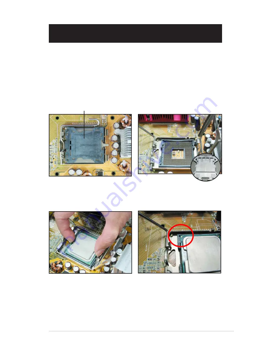
Intel LGA775 Socket

1. 

Locate the CPU socket on the 
motherboard. 

Release the load lever from the 
retention tab and lift the load plate. 
Then push the PnP cap from the 
load plate window to remove


To prevent damage to the socket 
pins, do not remove the PnP cap 
unless you are installing a CPU.

3. 

Position the CPU over the socket.

4. 

Ensure that the gold triangle is 
on the bottom‑left corner of the 
socket. 

Chapter 1: 

Quick Start

1.1 

Installing the CPU

Pick and Place Cap (PnP Cap)

Содержание M4A78LT-M

Страница 1: ...Motherboard Motherboard installation guide ...

Страница 2: ...CHANTABILITY OR FITNESS FOR A PARTICULAR PURPOSE IN NO EVENT SHALL ASUS ITS DIRECTORS OFFICERS EMPLOYEES OR AGENTS BE LIABLE FOR ANY INDIRECT SPECIAL INCIDENTAL OR CONSEQUENTIAL DAMAGES INCLUDING DAMAGES FOR LOSS OF PROFITS LOSS OF BUSINESS LOSS OF USE OR DATA INTERRUPTION OF BUSINESS AND THE LIKE EVEN IF ASUS HAS BEEN ADVISED OF THE POSSIBILITY OF SUCH DAMAGES ARISING FROM ANY DEFECT OR ERROR IN ...

Страница 3: ... your area If you are not sure about the voltage of the electrical outlet you are using contact your local power company If the power supply is broken do not try to ix it by yourself Contact a qualiied service technician or your retailer Operation safety Before installing the motherboard and adding devices on it carefully read all the manuals that came with the package Before using the product ens...

Страница 4: ...4 ...

Страница 5: ... lift the load plate Then push the PnP cap from the load plate window to remove To prevent damage to the socket pins do not remove the PnP cap unless you are installing a CPU 3 Position the CPU over the socket 4 Ensure that the gold triangle is on the bottom left corner of the socket Chapter 1 Quick Start 1 1 Installing the CPU Pick and Place Cap PnP Cap ...

Страница 6: ...cket and damaging the CPU 1 1 2 Intel LGA1366 Socket 1 Locate the CPU socket on the motherboard To prevent damage to the socket pins do not remove the PnP cap unless you are installing a CPU Press the load lever with your thumb A then move it to the left B until it is released from the retention tab A B Load lever Retention tab 3 Lift the load lever in the direction of the arrow to a 13 º angle 4 ...

Страница 7: ...d damaging the CPU Position the CPU over the socket ensuring that the gold triangle is on the bottom left corner of the socket and then it the socket alignment key into the CPU notch Remove the PnP cap from the CPU socket PnP cap Gold triangle mark Alignment key CPU notch 8 Close the load plate A and then push the load lever B until it snaps into the retention tab A B ...

Страница 8: ...tion tab 3 Lift the load lever in the direction of the arrow until the load plate is completely lifted Position the CPU over the socket ensuring that the gold triangle is on the bottom left corner of the socket and then it the socket alignment keys into the CPU notches The CPU its in only one correct orientation DO NOT force the CPU into the socket to prevent bending the connectors on the socket a...

Страница 9: ...s toxic and inedible DO NOT eat it If it gets into your eyes or touches your skin wash it off immediately and seek professional medical help Some heatsinks come with pre applied thermal paste If so skip this step Apply some Thermal Interface Material to the exposed area of the CPU that the heatsink will be in contact with ensuring that it is spread in an even thin layer 8 Insert the load lever und...

Страница 10: ...e the CPU The lever clicks on the side tab to indicate that it is locked The CPU its in only one correct orientation DO NOT force the CPU into the socket to prevent bending the connectors on the socket and damaging the CPU 1 1 4 AMD AM2 Socket 1 Locate the CPU socket on the motherboard Press the lever sideways to unlock the socket then lift it up to a 90º angle Ensure that the socket lever is lift...

Страница 11: ...ology For Intel certiied heatsink Some heatsinks will come with pre applied thermal paste If so do not scrape it off and remove the protective ilm only before installation If not before installing the heatsink apply several drops of thermal paste to the exposed area of the CPU that the heatsink will be in contact with Ensure that it is spread in an even thin layer To prevent contaminating the past...

Страница 12: ...le to the corresponding connector on the motherboard DO NOT forget to connect the CPU fan connector Hardware monitoring errors can occur if you fail to plug this connector and we suggest you use an omni directional heatsink to gain the maximum heat dissipation area 1 2 3 4 For AMD certiied heatsink Follow the instructions below to install an AMD certiied heatsink ...

Страница 13: ...he DIMM into the socket until the retaining clip snaps back in place and the DIMM is properly seated Locked Retaining Clip 3 Firmly insert the DIMM into the socket until the retaining clips snap back in place and the DIMM is properly seated Locked Retaining Clip 1 Unlock a DIMM socket by pressing the retaining clips outward Align a DIMM on the socket such that the notch on the DIMM matches the bre...

Страница 14: ...ws until they are inger tight You may remove the metal slot covers for the expansion cards at the back of the chassis before installing the motherboard For some chassis models it might be dificult to remove the expansion slot cover after the installation DO NOT over tighten the screws Doing so may damage the motherboard 1 4 Installing the motherboard 1 I O ports differ with motherboards Use and in...

Страница 15: ... input voltage Power supply with active PFC Active PFC automatically corrects the AC input voltage If you are using a power supply with passive PFC adjust to the correct AC input voltage in your area Failure to adjust the power supply to the correct AC input voltage will seriously damage the system Use power supply units with safety certiication only Using unstable power supply units can damage yo...

Страница 16: ...roperly seated on the slot 3 Screw to secure the card on the slot 4 Repeat the previous steps to install another expansion card Refer to the card documentation for the card coniguration details and to the motherboard user guide in case you need to configure any jumpers after installing the expansion card Refer to the motherboard user guide for the instructions of the expansion card signal cable co...

Страница 17: ...les and secure the disk drive with screws 3 Orient and plug the IDE cable into the optical drive The red stripe on the IDE cable is the pin1 end and should match the dimple marking Pin1 on the optical drive 4 Connect the 4 pin power cable to the optical drive Attach the audio cable to the connector on the optical drive IDE cables are dummy proof Never force the IDE cable into the connector ...

Страница 18: ... the bay Align with the screw holes and secure the disk drive with screws 3 Orient and plug the SATA cable into the optical drive SATA cables are dummy proof Never force a SATA cable into the connector 4 Connect the SATA power cable to the the optical drive Attach the audio cable to the connector on the optical drive ...

Страница 19: ...into the bay Align with the screw holes and secure the disk drive with screws 3 Orient and plug the loppy interface cable into the loppy disk drive The red stripe on the cable is the pin1 end and should match pin1 on the loppy disk drive 4 Connect the loppy power cable to the connector at the back of the loppy disk drive ...

Страница 20: ...h screws 3 Orient and connect the signal cable to the hard disk drive The red stripe on the cable is the pin1 end Match the dummy proof notch and do not force the cable into the connector 4 Connect the 4 pin power cable to the connector at the back of the hard disk drive Attach the other end of the signal cable to the corresponding slot on the motherboard ...

Страница 21: ... performance The 40 wire cables are usually for the optical drives The cables are designed with pull tabs Just easily install the disk drives based on the cable labels To prevent damaging the pins pull the cable tabs to disconnect the cable If your operating system is installed to the hard disk drive controlled by the RAID or other controllers you have to install the controller driver to the hard ...

Страница 22: ...the connector at the back of the hard disk drive Notes for installing SATA hard disk drive Serial ATA SATA interface provides higher data transmission speed and better voltage tolerance The narrow design of the SATA cable also solves cabling issues and allows better airlow in the chassis The SATA power cable connector is different from the traditional 4 pin power connector ASUS motherboard bundles...

Страница 23: ...es of your chassis may differ with models or designs Connect these connectors to the motherboard according to the label If the LEDs do not light up and the pin location is correct you might have mistaken the ground pins with the signal pins Usually the white wire stands for the ground pins and the color coded wire for the signal pins The SPEAKER RESET and PWRSW front panel cables have no speciic o...

Страница 24: ...rs to the motherboard DO NOT force the male power connectors into the female counterparts on the motherboard Usually there will be two connectors on the motherboard 4 pin and 4 pin power connectors Some older power supply units may only have 20 pin power connector which also its the 24 pin power connector on the motherboard 24 pin power connector 20 pin power connector on the 24 pin female counter...

Страница 25: ...Ensure the power connectors are irmly secured to the motherboard If your power supply supports 0 pin 4 pin you are able to combine these two connectors and install to the 4 pin connectors on the motherboard Power connectors 20 4 24 pin ATX connector 4 pin ATX connector peripheral power connector left loppy power connector right ...

Страница 26: ... in port 11 LAN RJ45 port 10 IEEE1394 port 9 Parallel port 1 AC Power plug power extension cord PS keyboard port keyboard 3 S PDIF out port digital 1 speaker system 4 Serial port PDA dock USB port USB devices Microphone port microphone 7 Line out port speaker 8 PS mouse port mouse 9 Parallel port printer 10 IEEE1394 port external hard disk drive 11 LAN RJ4 port modem 1 Line in port recorder 13 VGA...

Страница 27: ...monitor is black Ensure the monitor power is on and the VGA cable is connected correctly Adjust the monitor brightness and contrast Shut down the computer and remove the power cord Check whether the VGA card is installed irmly No memory detected Ensure the memory module is correct Ensure the DIMMS are irmly seated on the DIMM socket Ensure the memory module is from the qualiied vedor list Refer to...

Страница 28: ... 8 Chapter 1 Quick Start ...

Страница 29: ...not more than eight alphanumeric characters for the main ilename and three alphanumeric characters for the extension name A afudos oOLDBIOS1 rom Ensure that the loppy disk is not write protected and has at least 1024KB free space to save the ile The succeeding BIOS screens are for reference only The actual BIOS screen displays may not be same as shown The utility returns to the DOS prompt after co...

Страница 30: ...iP5K3D ROM AMI Firmware Update Utility Version 1 19 ASUS V2 07 03 11 24BB Copyright C 2002 American Megatrends Inc All rights reserved WARNING Do not turn off power during lash BIOS Reading ile done Reading lash done Advance Check Erasing lash done Writing lash done Verifying lash done Please restart your computer A A afudos iP5K3D ROM AMI Firmware Update Utility Version 1 19 ASUS V2 07 03 11 24BB...

Страница 31: ...awdlash exe from the Software folder of the support CD to the loppy disk CD ROM or a USB lash disk with the latest BIOS ile 3 Boot the system in DOS mode using the bootable loppy disk CD ROM or a USB lash disk you created earlier 4 Under the DOS mode use X X stands for the name of the disk assignment to switch to the folder of loppy disk CD ROM or USB lash disk you saved the BIOS ile and AwardBIOS...

Страница 32: ... the system AwardBIOS Flash Utility for ASUS V1 14 C Phoenix Technologies Ltd All Rights Reserved F1 Reset For NF590 SLI M2N32 SLI DELUXE DATE 03 30 2006 Flash Type PMC Pm49FL004T LPC FWH File Name to Program M2N32SLI bin Flashing Complete Press F1 to Continue Write OK No Update Write Fail For NF590 SLI M2N32 SLI DELUXE DATE 03 30 2006 Flash Type PMC Pm49FL004T LPC FWH File Name to Program M2N32SL...

Страница 33: ...rdBIOS Flash Utility for ASUS V1 14 C Phoenix Technologies Ltd All Rights Reserved Message For NF590 SLI M2N32 SLI DELUXE DATE 03 30 2006 Flash Type PMC Pm49FL004T LPC FWH File Name to Program 0112 bin Save current BIOS as AwardBIOS Flash Utility for ASUS V1 14 C Phoenix Technologies Ltd All Rights Reserved Message Please Wait For NF590 SLI M2N32 SLI DELUXE DATE 03 30 2006 Flash Type PMC Pm49FL004...

Страница 34: ...ity allows you to manage save and update the motherboard BIOS in Windows environment The ASUS Update utility allows you to Save the current BIOS ile Download the latest BIOS ile from the Internet Update the BIOS from an updated BIOS ile Update the BIOS directly from the Internet and View the BIOS version information This utility is available in the support CD DVD that comes with the motherboard pa...

Страница 35: ...t you to avoid network trafic or click Auto Select Click Next Updating the BIOS through the Internet To update the BIOS through the Internet 1 To aunch the ASUS Update utility from the Windows desktop click Start Programs ASUS ASUSUpdate ASUSUpdate The ASUS Update main window appears Select Update BIOS from the drop down menu list then click Next ...

Страница 36: ...OS from the drop down menu list then click Next 4 From the FTP site select the BIOS version that you wish to download Click Next Follow the screen instructions to complete the update process The ASUS Update utility is capable of updating itself through the Internet Always update the utility to avail of all its features 3 Locate the BIOS ile from the Open window then click Open 4 Follow the screen ...

Страница 37: ...It saves time and hassles for you on contacting ASUS technical support team or returning the product for warranty service 3 1 1 Basic troubleshooting A Bad connection 1 Ensure there is no contaminants on the gold contact or the pins Use a cotton bud or an eraser and gently rub the gold contact Remember to brush away the eraser crumbs VGA card gold contact DIMM gold contact LGA775 processor gold co...

Страница 38: ...es the broken or bended pins are NOT REPAIRABLE Connector pins B CPU overheated 1 Wipe clean the CPU surface with the clean cloth Apply several drops of thermal paste to the exposed area of the CPU that the heatsink will be in contact with Ensure that it is spread in an even thin layer CPU surface Top view of heatsink and fan Side view of heatsink and fan Ensure there is no contaminants on the hea...

Страница 39: ... table below for further check Check Items Reference page Power LED Screen display Heatsink and fan BIOS beeps Error messages No power Off No Stop No N A 3 4 No screen display On No Stop No N A 3 On No Running No N A 3 On No Running Yes N A 3 Failure to enter OS On Yes Running Yes Yes 3 On Yes Running No Yes 3 On Yes Running No No 3 If the problem has been ixed but a new problem emerges go over th...

Страница 40: ...to do so will seriously damage the power supply unit Failure to adjust the power supply to the correct AC input voltage will seriously damage the system Ensure you have attached the power cord to the wall outlet Connect the power plug directly to the wall outlet DO NOT connect it to the power extension uninterruptible power supply UPS or other devices Exchange the power plugs of the system and the...

Страница 41: ...vices in turn to ind out the defective device in the order of memory module CPU motherboard hard optical disk drive keyboard mouse When you ind out the defective device contact your device retailer for service 3 2 3 Failure to enter the operating system 1 If the problem emerges after you add a hardware remove the newly added hardware and reboot the system If the system is working normally without ...

Страница 42: ...ide for details If you install 4 0 GB memory and it reports 3 X GB it is normal Q2 The system cannot detect the loppy disk drive but the loopy disk stays lit A2 The loopy disk cables are not properly installed Ensure the red stripe on the cable pin1 end should match pin1 on the loppy disk drive Q3 Fail to enter the operating system after the USB lash disk or external hard disk drives A3 When the s...

Страница 43: ...sh 4 Place the computer on a stable surface Keep the computer away from areas of extreme temperature C to 30 C is the best surroundings temperature Use an air conditioner or a electric fan to gain a better heat dissipation 6 Arrange the ribbon cables neatly to avoid insuficient airlow 4 3 Usage knowledge 1 Turn on and shut down your computer regularly If your computer needs to be on for a long tim...

Страница 44: ...mputer will not be used for a long time put some desiccant moisture absorbers in the chassis to prevent humidity damage In some hot and humid climatic areas you had better turn on your computer every other week Doing so also helps prevent humidity damage ...

Страница 45: ...puter will not be used for a long time put some desiccant moisture absorbers in the chassis to prevent humidity damage 2 In some hot and humid climatic areas you had better turn on your computer every other week Doing so also helps prevent humidity damage ...

Отзывы: