background image

ASUS ESC500 G2

4-17

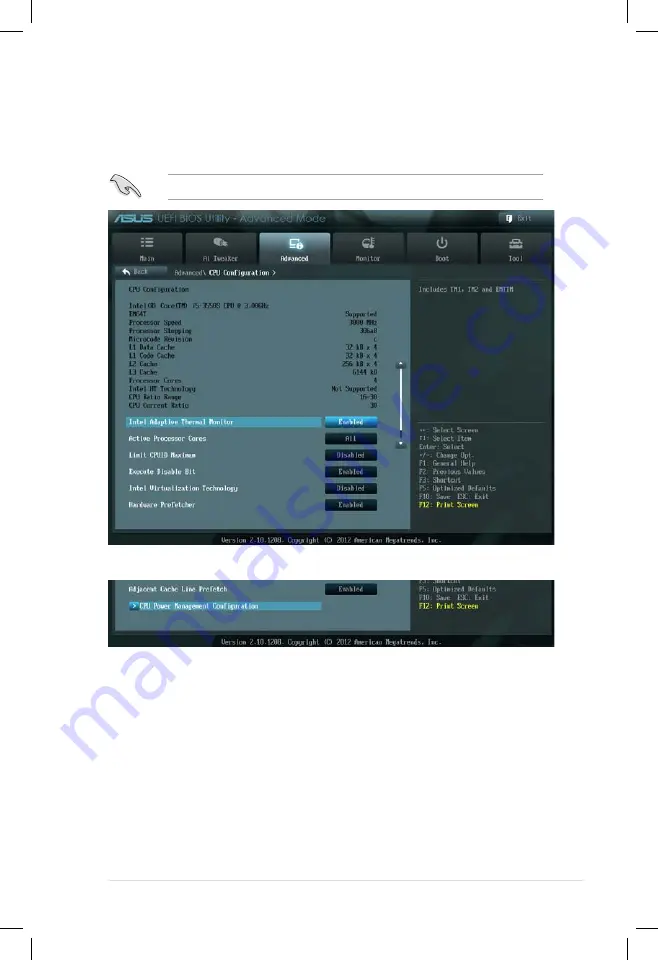
4.5.2 

CPU Configuration

The items in this menu show the CPU-related information that the BIOS 

automatically detects.

The items shown in this screen may be different due to the CPU you installed.

Scroll down to display the following items:

Intel Adaptive Thermal Monitor [Enabled]

[Disabled] 

Disables the CPU thermal monitor function.

[Enabled] 

Enables the overheated CPU to throttle its clock speed to cool 

down.

Active Processor Cores [All]

Allows you to choose the number of CPU cores to activate in each processor 

package. Configuration options: [All] [1] [2] [3]

Limit CPUID Maximum [Disabled]

[Disabled] 

Disables this function.

[Enabled] 

Allows legacy operating systems to boot even without support for 

CPUs with extended CPUID functions.

Содержание ESC500

Страница 1: ...ESC500 G2 Workstation User Manual ...

Страница 2: ...uption of business and the like even if ASUS has been advised of the possibility of such damages arising from any defect or error in this manual or product Specifications and information contained in this manual ae furnished for informational use only and are subject to change at any time without notice and should not be construed as a commitment by ASUS ASUS assumes no responsibility or liability...

Страница 3: ... 1 2 1 2 Serial number label 1 2 1 3 System specifications 1 3 1 4 Front panel features 1 5 1 5 Rear panel features 1 6 1 6 Internal features 1 7 1 7 LED information 1 8 1 7 1 Front panel LED 1 8 1 7 2 LAN RJ 45 LEDs 1 8 Chapter 2 Hardware setup 2 1 Chassis cover 2 2 2 2 Motherboard overview 2 4 2 3 Central Processing Unit CPU 2 5 2 3 1 CPU installation 2 6 2 3 2 Installing the CPU heatsink and fa...

Страница 4: ...ard LEDs 3 7 3 4 Jumpers 3 10 3 5 Internal connectors 3 12 3 5 1 Rear panel connection 3 23 3 5 2 Audio I O connections 3 24 Chapter 4 BIOS infomation 4 1 Knowing BIOS 4 2 4 2 BIOS setup program 4 3 4 2 1 EZ Mode 4 4 4 2 2 Advanced Mode 4 5 4 3 Main menu 4 7 4 3 1 System Language English 4 7 4 3 2 System Date Day xx xx xxxx 4 7 4 3 3 System Time xx xx xx 4 7 4 4 Ai Tweaker menu 4 10 4 5 Advanced m...

Страница 5: ... 1 RAID definitions 5 2 5 1 2 Installing Serial ATA hard disks 5 3 5 1 3 Setting the RAID item in BIOS 5 3 5 1 4 Intel Rapid Storage Technology Option ROM utility 5 3 Chapter 6 Driver installation 6 1 Creating a RAID driver disk 6 2 6 1 1 Creating a RAID driver disk without entering the OS 6 2 6 1 2 Creating a RAID driver disk in Windows 6 2 6 1 3 Installing the RAID driver during Windows OS insta...

Страница 6: ...US Update 6 12 6 3 5 MyLogo 6 13 6 4 Audio configurations 6 15 6 5 System recovery 6 17 6 4 1 Using the Recovery Partition 6 17 6 4 2 Using the Recovery DVD 6 17 Appendix Reference information A 1 Simple fixes A 2 ...

Страница 7: ...he user is encouraged to try to correct the interference by one or more of the following measures Reorient or relocate the receiving antenna Increase the separation between the equipment and receiver Connect the equipment to an outlet on a circuit different from that to which the receiver is connected Consult the dealer or an experienced radio TV technician for help Canadian Department of Communic...

Страница 8: ...efore operating the server carefully read all the manuals included with the server package Before using the server make sure all cables are correctly connected and the power cables are not damaged If any damage is detected contact your dealer as soon as possible To avoid short circuits keep paper clips screws and staples away from connectors slots sockets and circuitry Avoid dust humidity and temp...

Страница 9: ...nus and describes the BIOS parameters 5 Chapter 5 RAID configuration This chapter provides information on how to configure your hard disk drives as RAID sets 6 Chapter 6 Driver installation This chapter provides information on how to install the drivers for system components This chapter also describes the software applications that the barebone workstation supports 7 Appendix Reference informatio...

Страница 10: ...e that you perform certain tasks properly take note of the following symbols used throughout this manual Typography Bold text Indicates a menu or an item to select Italics Used to emphasize a word or a phrase Key Keys enclosed in the less than and greater than sign means that you must press the enclosed key Example Enter means that you must press the Enter or Return key Key1 Key2 Key3 If you must ...

Страница 11: ...1 ASUS ESC500 G2 This chapter describes the general features of the workstation including sections on front panel and rear panel specifications Chapter 1 Product introduction ...

Страница 12: ... product ASUS Technical Support team members can then offer a quicker and satisfying solution to your problems xxS0xxxxxxxxxx ESC500 G2 Model Name ESC500 G2 Chassis ASUS T10A Pedestal Chassis Motherboard ASUS P8C WS Component 1 x 500W 700W 80Plus Single Power Supply Bronze Silver 1 x 120x120mm System Fan 1 x Intel LGA1155 CPU Cooler Accessories 1 x ASUS ESC500 G2 User s Guide 1 x ESC500 G2 Support...

Страница 13: ...essor Family Intel Core G8x0 Processor Family Intel Core G6x0 Processor Family Core Logic Intel C216 Express Chipset Memory Total Slots 4 DIMMs 2 Channels Capacity Maximum up to 32GB Memory Type DDR3 1066 1333 1600 ECC non ECC UDIMM Refer to www asus com for detail memory AVL CPU support list Memory Size 1GB 2GB 4GB 8GB UDIMM Expansion Slots Total PCI PCI X PCI E Slots 6 Slot Type 1 x PCIe 3 0 x16...

Страница 14: ...3 0 2 0 ports 1 x IEEE1394a 2 x RJ 45 ports 1 x DVI I port 1 x 8 channel Audio I O Anti virus Software Optional Anti Virus CD Pack EMI Europe CE EN55022 EN55024 V Taiwan BSMI V China CCC V Dimension HH x WW x DD 423mm x 190mm x 435mm Net Weight Kg CPU DRAM HDD excluded 10 8 Kg Power Supply 500W 80Plus Single Power Supply Bronze 700W 80Plus Single Power Supply Silver Environment Operating temperatu...

Страница 15: ...ptical drive card reader and four USB ports are located on the front panel For future installation of 5 25 inch devices two drive bays are available Refer to section 1 7 1 Front panel LED for the LED descriptions Optical Drive Empty 5 25 inch bay Smart Card Reader optional Power LED blue HDD access LED orange Reset button Microphone Headphone ports Power button USB 2 0 USB 3 0 ports ...

Страница 16: ...ouse combo port USB ports DVI I ports Audio ports S PDIF Out ports and Gigabit LAN ports do not appear on the rear panel if motherboard is not present Power supply module Expansion slots Power supply switch Power cord connector PS 2 keyboard mouse port USB 2 0 ports Audio I O ports USB 3 0 ports LAN RJ 45 port 2 IEEE 1394a port System fan LAN RJ 45 port 1 Coaxial S PDIF Out port Optical S PDIF Out...

Страница 17: ...includes the basic components as shown 1 Power supply unit 2 120mm system fan 3 ASUS P8C WS motherboard 4 CPU heatsink and fan assembly 5 Optical drive optional 6 5 25 inch drive bays 7 Smart card reader optional 8 Front I O board 9 Internal HDD bays 6 1 2 3 4 5 7 8 9 ...

Страница 18: ... ON System power ON HDD Access LED Orange OFF Blinking No activity Read write data into the HDD ACT LINK LED SPEED LED Status Description Status Description OFF No link OFF 10 Mbps connection YELLOW Linked ORANGE 100 Mbps connection BLINKING Data activity GREEN 1 Gbps connection SPEED LED ACT LINK LED ACT LINK LED SPEED LED Power LED HDD Access LED ...

Страница 19: ...ASUS ESC500 G2 2 This chapter lists the hardware setup procedures that you have to perform when installing or removing system components Chapter 2 Hardware setup ...

Страница 20: ...unplug the power cord before removing the side cover Take extra care when removing the side cover Keep your fingers from components inside the chassis that can cause injury such as the CPU fan rear fan and other sharp edged parts To remove the left side cover 1 Remove the two screws that secure the left side cover to the chassis 1 1 2 Unlock the side cover lock 2 2 ...

Страница 21: ...2 3 ASUS ESC500 G2 3 Slide the left side cover for about half an inch toward the rear until it is disengaged from the chassis Carefully lift the cover and set it aside 3 ...

Страница 22: ... screws as indicated by the circles in the illustration below Ensure to unplug the power cord before installing or removing any motherboard component or connection Failure to do so can cause you physical injury and damage motherboard components Refer to Chapter 3 Motherboard information for detailed information on the motherboard Place this side towards the rear of the chassis ...

Страница 23: ... cap is missing or if you see any damage to the PnP cap socket contacts motherboard components ASUS will shoulder the cost of repair only if the damage is shipment transit related Keep the cap after installing the motherboard ASUS will process Return Merchandise Authorization RMA requests only if the motherboard comes with the cap on the LGA1155 socket The product warranty does not cover damage to...

Страница 24: ...e the order in opening closing the double latch Follow the instructions printed on the metal sealing hatch or the illustrations shown below in this manual The plastic cap will pop up automatically once the CPU is in place and the hatch properly sealed down A B 1 2 ...

Страница 25: ...2 7 ASUS ESC500 G2 3 4 ...

Страница 26: ...Chapter 2 Hardware setup 2 8 C B A 5 6 ...

Страница 27: ...2 Installing the CPU heatsink and fan assembly To install the CPU heatsink and fan assembly Apply the Thermal Interface Material to the CPU heatsink and CPU before you install the heatsink and fan if necessary 2 B B A A 1 3 4 ...

Страница 28: ...Chapter 2 Hardware setup 2 10 To uninstall the CPU heatsink and fan assembly 2 A B B A 1 ...

Страница 29: ...ns 2 4 System memory 2 4 1 Overview The motherboard comes with four Double Data Rate 3 DDR3 Dual Inline Memory Modules DIMM slots A DDR3 module is notched differently from a DDR or DDR2 module DO NOT install a DDR or DDR2 memory module to the DDR3 slot ...

Страница 30: ...u install 4GB or more memory on the motherboard the actual usable memory for the OS can be about 3GB or less For effective use of memory we recommend that you do any of the following Use a maximum of 3GB system memory if you are using a 32 bit Windows OS Install a 64 bit Windows OS when you want to install 4GB or more on the motherboard For more details refer to the Microsoft support site at http ...

Страница 31: ...ket in the wrong direction to avoid damaging the DIMM Ensure to unplug the power supply before adding or removing DIMMs or other system components Failure to do so may cause severe damage to both the motherboard and the components Always insert the DIMM into the socket VERTICALLY to prevent DIMM notch damage 1 2 3 2 4 4 To remove a DIMM B A ...

Страница 32: ...ation system provides three 3 internal Serial ATA hard disk drive bays To install a Serial ATA hard disk drive 1 Refer to the previous section to remove the side cover 2 Pull out the bay locks on the HDD cage 3 Lift up the secure tab on the HDD cage 4 Swing out the HDD cage ...

Страница 33: ...ack the HDD cage 7 Push in the bay locks to secure the hard disk drive 8 Connect a 7 pin SATA cable from the motherboard SATA port and a 15 pin power plug from the power supply unit to the back connectors of the hard disk drive Use either the 15 pin SATA power connector OR the legacy 4 pin power connector DO NOT use both to prevent damage to components and to keep the system from becoming unstable...

Страница 34: ...uppermost bay labeled 1 The lower bays labeled 2 and 3 are available for additional 5 25 inch optical zip or floppy disk drives You must remove the front panel assembly before installing a 5 25 inch drive 2 6 1 Removing the front panel cover To remove the front panel cover 2 3 2 Gently lift the front panel assembly until the hinge like tabs on the top side of the assembly are detached from the cha...

Страница 35: ...e drive into the bay until its screw holes align with the holes on the bay 2 6 2 Installing 5 25 inch drives To install 5 25 inch drives 4 Push in the bay locks to secure the optical drive 1 Select the drive bay you intend to use and remove the drive slot plate cover 2 Release the bay locks ...

Страница 36: ...DO NOT use both to prevent damage to components and to keep the system from becoming unstable 5 Connect a 7 pin SATA cable from the motherboard SATA port and a 15 pin power plug from the power supply unit to the back connectors of the hard disk drive 6 Reinstall the front panel cover and side covers when done ...

Страница 37: ...xpansion cards Failure to do so may cause you physical injury and damage motherboard components Slot No Slot Description 1 PCIe 3 0 x16_1 slot single at x16 or dual at x8 x8 mode 2 PCIe 3 0 x16_2 slot x8 mode 3 PCIe 2 0 x1_1 slot 4 PCIe 2 0 x16_3 slot x4 mode 5 PCI1 slot 6 PCIe 2 0 x16_4 slot x4 mode ...

Страница 38: ...mentation that came with it and make the necessary hardware settings for the card 2 Remove the left side cover from the chassis 3 Lay the system on its side on a flat stable surface 4 Select the slot that you intend to use and then remove the metal bracket next to the slot 5 Align the card golden fingers to the slot and its metal bracket to the slot opening on the chassis 6 Press the card firmly u...

Страница 39: ...wo PCI groups making the system unstable and the card inoperable Refer to the table on the next page for details By default if you install a discrete graphics card on the PCIe x16 slot the onboard GPU will be automatically disabled Connect the VGA cable to the discrete graphics card first when using a discrete graphics card Standard Interrupt assignments IRQ Priority Standard function 0 1 System T...

Страница 40: ... PCIEx16_1 shared PCIEx16_2 shared PCIEx16_3 shared PCIEx16_4 shared PCIEx1_1 shared PCI1 shared VIA1394 shared USB3 0 shared LAN1 82574 shared LAN2 82574 shared SATA Controller 1 shared SATA Controller 2 shared USB 2 0 Controller 1 shared USB 2 0 Controller 2 shared HD Audio shared ...

Страница 41: ...g a defective component This section tells how to remove the system fan To remove the system fan 1 Disconnect the chassis fan cable from the CHA_FAN1 connector on the motherboard 2 Locate and remove four system fan screws at the rear panel Keep the screws for later use Hold the system fan with one hand while removing the system screws 3 Remove the system fan and then set aside ...

Страница 42: ...ipment You do not need to disconnect these cables unless you will remove pre installed components to install additional devices Refer to Chapter 3 for detailed information on the connectors Standard cables connected to the motherboard 1 24 pin EATX power plug 2 8 pin EATX 12V power plug 3 Front panel USB 2 0 cable 4 Front panel USB 3 0 cable 5 Front panel audio module cable 6 System fan cable 7 CP...

Страница 43: ... ESC500 G2 This chapter gives information about the motherboard that comes with the workstation This chapter includes the motherboard layout jumper settings and connector locations Chapter 3 Motherboard info ...

Страница 44: ...Chapter 3 Motherboard information 3 2 3 1 Motherboard layouts P8C WS Motherboard Refer to 3 5 Connectors for more information about internal connectors and rear panel connectors ...

Страница 45: ...l C216 Serial ATA 3 0 Gb s connectors 7 pin SATA3G_3 6 blue 3 13 9 Onboard LED 3 7 10 System panel connector 20 8 pin PANEL 3 22 11 Clear RTC RAM 3 pin CLRTC 3 10 12 USB 2 0 connectors Type A 10 1 pin USB1314 Type B USB11 USB12 3 14 13 Parallel port connector 26 1 pin LPT1 3 15 14 TPM connector 20 1 pin TPM 3 19 15 Serial port connector 10 1 pin COM1 3 18 16 Digital audio connector 4 1 pin SPDIF_O...

Страница 46: ...ocking and gaming performance when working on a bare or open case system 1 EPU switch Turning this switch to Enable will automatically detect the current PC loadings and intelligently moderate the power consumption For ensuring the system performance turn the switch setting to Enable when the system is powered off ...

Страница 47: ...will automatically optimize the system for fast yet stable GPU speed For ensuring the system performance turn the switch setting to Enable when the system is powered off The GPU Boost Switch functions only when you install the DESKTOP CPU that supports onboard graphics ...

Страница 48: ...next set of failsafe settings The blinking speed of the DRAM_LED increases indicating different test processes Due to memory tuning requirement the system automatically reboots when each timing set is tested If the installed DIMMs still fail to boot after the whole tuning process the DRAM_LED lights continuously Replace the DIMMs with ones recommended in the Memory QVL Qualified Vendors Lists in t...

Страница 49: ...tatus of these key components during POST Power on Self Test CPU memory modules VGA card and hard disk drive If an error is found the critical component s LED stays lit up until the problem is solved 2 GPU Boost LED The GPU Boost LED lights up when the GPU Boost switch is turned to Enable ...

Страница 50: ... The motherboard comes with a standby power LED that lights up to indicate that the system is ON in sleep mode or in soft off mode This is a reminder that you should shut down the system and unplug the power cable before removing or plugging in any motherboard component The illustration below shows the location of the onboard LED ...

Страница 51: ...0 G2 5 DRAM LED The DRAM_LED lights up when the installed DIMMs incompatible with the motherboard or improperly installed When using the MemOK switch for automatic memory compatibility tuning the DRAM_LED will blink ...

Страница 52: ...ter 4 Hold down the Del key during the boot process and enter BIOS setup to re enter data Except when clearing the RTC RAM never remove the cap on CLRTC jumper default position Removing the cap will cause system boot failure If the steps above do not help remove the onboard battery and move the jumper again to clear the CMOS RTC RAM data After the CMOS clearance reinstall the battery You do not ne...

Страница 53: ...mper for a 4 pin fan the fan control will not work and the fan you installed will always run at full speed 2 Chassis Fan control setting 3 pin CHAFAN_SEL These jumpers allow you to switch for fan pin selection The CHAFAN_SEL jumper is for the front fans and rear fans control Set to pins 1 2 when using 3 pin fans or pins 2 3 when using 4 pin fans ...

Страница 54: ...onnectors set the SATA Mode item in the BIOS to RAID Mode Refer to section 4 5 4 SATA Configuration for details Before creating a RAID set refer to section 5 5 RAID configurations or the manual bundled in the motherboard support DVD When using NCQ set the SATA Mode in the BIOS to AHCI Mode Refer to section 4 5 4 SATA Configuration for details You must install Windows XP Service Pack 3 or later ver...

Страница 55: ...by default If you intend to create a Serial ATA RAID set using these connectors set the SATA Mode item in the BIOS to RAID Mode Refer to section 3 5 4 SATA Configuration for details Before creating a RAID set refer to section 5 5 RAID configurations or the manual bundled in the motherboard support DVD When using hot plug and NCQ set the SATA Mode in the BIOS to AHCI Mode Refer to section 4 5 4 SAT...

Страница 56: ... ports Never connect a 1394 cable to the USB connectors Doing so will damage the motherboard 3 USB 2 0 connectors Type A 10 1 pin USB1314 Type B USB11 USB12 These connectors are for USB 2 0 ports Connect the USB module cable to any of these connectors then install the module to a slot opening at the back of the system chassis These USB connectors comply with USB 2 0 specification that supports up ...

Страница 57: ...th this USB 3 0 connector you can have a front panel USB 3 0 solution You can connect the ASUS front panel USB 3 0 box to this connector to obtain the front panel USB 3 0 solution Due to Intel limitations the USB3_12 only supports Windows 7 operating system 5 Parallel port connector 26 1 pin LPT1 This connector is for a parallel port Connect the parallel port module cable to this connector then in...

Страница 58: ...stem chassis Never connect a USB cable to the IEEE 1394a connector Doing so will damage the motherboard The IEEE 1394a module is purchased separately 7 Digital audio connector 4 1 pin SPDIF_OUT This connector is for an additional Sony Philips Digital Interface S PDIF port Connect the S PDIF Out module cable to this connector then install the module to a slot opening at the back of the system chass...

Страница 59: ... CPU_FAN connector supports the CPU fan of maximum 2A 24 W fan power If you install two VGA cards we recommend that you plug the rear chassis fan cable to the motherboard connector labeled CHA_FAN1 CHA_FAN2 CHA_FAN3 for better thermal environment Do not forget to connect the fan cables to the fan connectors Insufficient air flow inside the system may damage the motherboard components These are not...

Страница 60: ...o avail of the motherboard s high definition audio capability If you want to connect a high definition front panel audio module to this connector set the Front Panel Type item in the BIOS setup to HD if you want to connect an AC 97 front panel audio module to this connector set the item to AC97 By default this connector is set to HD 10 Serial port connector 10 1 pin COM1 This connector is for a se...

Страница 61: ...tificates passwords and data A TPM system also helps enhance network security protects digital identities and ensures platform integrity This connector can also serve for G P Diagnosis card installtion G P Diagnosis card layout LED 0 and 1 Card connector Power Switch Press to turn ON or OFF the motherboard Reset Button Press to restart the motherboard ...

Страница 62: ...ard 04 S4 97 Initiate VGA BIOS 05 S5 9A 9D USB initiation 10 Resume from S1 A2 Detect IDE 30 Resume from S3 B2 Initiate option ROM 40 Resume from S4 1 Locate the TPM connector 20 1 pin TPM on the motherboard 2 With the LEDs of the diagnosis card facing to the PCIe slots align the card connector with the TPM connector and press firmly until the card sits on the connector completely Ensure to turn o...

Страница 63: ... power of 350 W Do not forget to connect the 8 pin EATX12 V power plug otherwise the system will not boot Use of a PSU with a higher power output is recommended when configuring a system with more power consuming devices The system may become unstable or may not boot up if the power is inadequate If you are uncertain about the minimum power supply requirement for your system refer to the Recommend...

Страница 64: ...m warning speaker 4 pin SPEAKER This 4 pin connector is for the chassis mounted system warning speaker The speaker allows you to hear system beeps and warnings ATX power button soft off button 2 pin PWRSW This connector is for the system power button Pressing the power button turns the system on or puts the system in sleep or soft off mode depending on the BIOS settings Pressing the power switch f...

Страница 65: ... 0 ports 7 and 8 2 IEEE 1394a port 8 USB 2 0 ports 5 and 6 3 LAN RJ 45 port 2 9 Coaxial S PDIF Out port 4 DVI port 10 Optical S PDIF Out port 5 LAN RJ 45 port 1 11 USB 3 0 ports 3 and 4 6 USB 2 0 ports 9 and 10 12 Audio I O ports and Refer to the tables on the next page for LAN port and audio port definitions ...

Страница 66: ...LED indications SPEED LED ACT LINK LED LAN port Activity Link LED Speed LED Status Description Status Description OFF No link OFF 10 Mbps connection ORANGE Linked ORANGE 100 Mbps connection BLINKING Data activity GREEN 1 Gbps connection Due to USB 3 0 controller limitation USB 3 0 devices can only be used under Windows OS environment and after the USB 3 0 driver installation USB 3 0 devices can on...

Страница 67: ...3 25 ASUS ESC500 G2 Connect to Headphone and Mic Connect to Stereo Speakers Connect to 2 1 channel Speakers Connect to 4 1 channel Speakers ...

Страница 68: ...Chapter 3 Motherboard information 3 26 Connect to 5 1 channel Speakers Connect to 7 1 channel Speakers ...

Страница 69: ...Chapter 3 This chapter tells how to change system settings through the BIOS Setup menus and describes the BIOS parameters Chapter 4 BIOS information ...

Страница 70: ...rage device configuration overclocking settings advanced power management and boot device configuration that are needed for system startup in the motherboard CMOS In normal circumstances the default BIOS settings apply to most conditions to ensure optimum performance We recommend that you not change the default BIOS settings except in the following circumstances An error message appears on the scr...

Страница 71: ...ou want to use the mouse to control the BIOS setup program If the system becomes unstable after changing any BIOS setting load the default settings to ensure system compatibility and stability Select the Load Optimized Defaults item under the Exit menu See section 4 9 Exit Menu for details If the system fails to boot after changing any BIOS setting try to clear the CMOS and reset the motherboard t...

Страница 72: ...options vary depending on the devices you installed to the system The Boot Menu F8 button is available only when the boot device is installed to the system Selects the Advanced mode functions Exits the BIOS setup program without saving the changes saves the changes and resets the system or enters the Advanced Mode Selects the display language of the BIOS setup program Displays the CPU motherboard ...

Страница 73: ...the screen has the following main items Main For changing the basic system configuration Ai Tweaker For changing the overclocking settings Advanced For changing the advanced system settings Monitor For displaying the system temperature power status and changing the fan settings Boot For changing the system boot configuration Tool For configuring options for special functions Exit For selecting the...

Страница 74: ...scroll bar appears on the right side of a menu screen when there are items that do not fit on the screen Press the Up Down arrow keys or Page Up Page Down keys to display the other items on the screen Navigation keys At the bottom right corner of the menu screen are the navigation keys for the BIOS setup program Use the navigation keys to select items in the menu and change the settings General he...

Страница 75: ...rview of the basic system information and allows you to set the system date time language and security settings 4 3 1 System Language English Allows you to choose the BIOS language version from the options Configuration options 4 3 2 System Date Day xx xx xxxx Allows you to set the system date 4 3 3 System Time xx xx xx Allows you to set the system time ...

Страница 76: ...when prompted To change an administrator password 1 Select the Administrator Password item and press Enter 2 From the Enter Current Password box key in the current password then press Enter 3 From the Create New Password box key in a new password then press Enter 4 Confirm the password when prompted 4 3 4 Security If you have forgotten your BIOS password erase the CMOS Real Time Clock RTC RAM to c...

Страница 77: ... shows Installed To set a user password 1 Select the User Password item and press Enter 2 From the Create New Password box key in a password then press Enter 3 Confirm the password when prompted To change a user password 1 Select the User Password item and press Enter 2 From the Enter Current Password box key in the current password then press Enter 3 From the Create New Password box key in a new ...

Страница 78: ...king related items Be cautious when changing the settings of the Ai Tweaker menu items Incorrect field values can cause the system to malfunction The configuration options for this section vary depending on the CPU and DIMM model you installed on the motherboard Scroll down to display the following items ...

Страница 79: ... 1400MHz DDR3 1600MHz Selecting a very high memory frequency may cause the system to become unstable If this happens revert to the default setting iGPU Max Frequency Auto Use the and keys to adjust the value The minimum frequency vary depending on the type of CPU installed Configuration options Auto depending on CPU 3000MHz only for desktop processors EPU Power Saving Mode Disabled Allows you to e...

Страница 80: ...lock DRAM Refresh Interval Auto Configuration options Auto 3120 DRAM Clock 9999 DRAM Clock DRAM WRITE Recovery Time Auto Configuration options Auto 5 DRAM Clock 16 DRAM Clock DRAM READ to PRE Time Auto Configuration options Auto 4 DRAM Clock 15 DRAM Clock DRAM FOUR ACT WIN Time Auto Configuration options Auto 16 DRAM Clock 63 DRAM Clock DRAM WRITE to READ Delay Auto Configuration options Auto 4 DR...

Страница 81: ...just the maximum non turbo CPU ratio Use and keys to adjust the value The valid value ranges vary according to your CPU model Enhanced Intel SpeedStep Technology Enabled Allows you to enable or disable the Enhanced Intel SpeedStep Technology Disabled Disables this function Enabled The operating system dynamically adjusts the processor voltage and core frequency which may result in decreased averag...

Страница 82: ...positive value To offset the voltage by a negative value CPU Voltage Auto Allows you to set the CPU voltage The values range from 0 005V to 0 635V with a 0 005V interval iGPU Offset Mode Sign To offset the voltage by a positive value To offset the voltage by a negative value iGPU Offset Voltage Auto This item appears only when you set the iGPU Offset Voltage to Offset Mode and allows you to set th...

Страница 83: ...0 77V to 1 60V with a 0 01V interval CPU PLL Voltage Auto Allows you to set the CPU PLL voltage The values range from 1 20V to 2 20V with a 0 01V interval Load Line Calibration Auto Load line is defined by Intel VRM spec and affects CPU voltage The CPU working voltage will decrease proportionally to CPU loading Higher load line calibration would get higher voltage and better overclocking performan...

Страница 84: ...stem to malfunction 4 5 Advanced menu The Advanced menu items allow you to change the settings for the CPU and other system devices 4 5 1 Trusted Computing TPM SUPORT Disabled Allows you to enable or disable the TPM support Configuration options Disabled Enabled This item appears only when you install TPM module to the motherboard ...

Страница 85: ...ptive Thermal Monitor Enabled Disabled Disables the CPU thermal monitor function Enabled Enables the overheated CPU to throttle its clock speed to cool down Active Processor Cores All Allows you to choose the number of CPU cores to activate in each processor package Configuration options All 1 2 3 Limit CPUID Maximum Disabled Disabled Disables this function Enabled Allows legacy operating systems ...

Страница 86: ...djacent cache line prefetching Disabled Disables this function CPU Power Management Configuration This item allows you to manage and configure the CPU s power CPU Ratio Auto Allows you to set the ratio between the CPU Core Clock and the BCLK Frequency Use and keys to adjust the ratio The valid value ranges vary according to your CPU model Enhanced Intel SpeedStep Technology Enabled Allows you to e...

Страница 87: ...3 RTC Wake Enabled Allows you to enable or disable Entry on S3 RTC Wake Configuration options Enabled Disabled Entry After Immediately Enable RTC wake timer at S3 enrty Configuration options Immediately 1 minute 2 minutes 5 minutes 10 minutes 15 minutes 30 minutes 1 hour 2 hours CPU C3 Report Auto Allows you to disable or enable the CPU C3 report to OS Auto Set this item automatically Enabled Enab...

Страница 88: ...e Page Threshold Support Enabled Allows you to enable or disable Active Page Threshold Support Configuration options Enabled Disabled Active Memory Threshold 0 Try to support RST when partition size Active Page Threshold size in MB When setting to Zero it will be in AUTO mode and check if partition size is enough at S3 entry Intel R Smart Connect Technology ISCT Configuration Disabled Allows you t...

Страница 89: ...ce on random workloads by allowing the drive to internally optimize the order of commands RAID Set to RAID when you want to create a RAID configuration from the SATA hard disk drives S M A R T Status Check Enabled S M A R T Self Monitoring Analysis and Reporting Technology is a monitor system When read write of your hard disk errors occur this feature allows the hard disk to report warning message...

Страница 90: ...play Auto Allows you to select which of the iGPU PCIE Graphics device should be the Primary Display Configuration options Auto PCIE PCI iGPU iGPU Memory 64M Allows you to select the iGPU share memory size Configuration options 32M 64M 96M 128M 160M 192M 224M 256M 288M 320M 352M 384M 416M 448M 480M 512M 1024M Render Standby Enabled Allows you to enable or disable the Render Standby by the internal ...

Страница 91: ...ct the presence of USB devices at startup If detected the USB controller legacy mode is enabled If no USB device is detected the legacy USB support is disabled Legacy USB3 0 Support Enabled Enabled Enables the support for USB 3 0 devices on legacy operating systems OS Disabled Disables the function Intel xHCI Mode Smart Auto Smart Auto Enables optimized xHCI Auto Allows the system to set the xHCI ...

Страница 92: ...ont panel audio connector AAFP mode to legacy AC 97 or high definition audio depending on the audio standard that the front panel audio module supports HD Sets the front panel audio connector AAFP mode to high definition audio AC97 Sets the front panel audio connector AAFP mode to legacy AC 97 VIA 1394 Controller Enabled Disabled Disables the controller Enabled Enables the onboard IEEE 1394a contr...

Страница 93: ...ed Allows you to enable or disable the serial port COM Configuration options Enabled Disabled Change Settings IO 3F8h IRQ 4 Allows you to select the Serial Port base address This item appears when Serial Port is set to Enabled Configuration options IO 3F8h IRQ 4 IO 2F8h IRQ 3 IO 3E8h IRQ 4 IO 2E8h IRQ 3 Parallel Port Configuration The sub items in this menu allow you to set the parallel port confi...

Страница 94: ...ff or on state whatever the system state was before the AC power loss Power On By PS 2 Keyboard Disabled Disabled Disables the Power On by a PS 2 keyboard Space Bar Sets the Space Bar on the PS 2 keyboard to turn on the system Ctrl Esc Sets the Ctrl Esc key on the PS 2 keyboard to turn on the system Power Key Sets Power key on the PS 2 keyboard to turn on the system This feature requires an ATX po...

Страница 95: ... PXE Support Configuration options Disable Link Enabled Power On By PCI Disabled Disabled Disables the PCI devices to generate a wake event Enabled Enables the PCI devices to generate a wake event Power On By PCIE Disabled Disabled Disables the PCIE devices to generate a wake event Enabled Enables the PCIE devices to generate a wake event Power On By Ring Disabled Disabled Disables Ring to generat...

Страница 96: ...plays the CPU and motherboard temperatures Select Ignore if you do not wish to display the detected temperatures CPU Fan Speed xxxx RPM or Ignore N A Chassis Fan 1 2 3 Speed xxxx RPM or Ignore N A Power Fan Speed xxxx RPM or Ignore N A The onboard hardware monitor automatically detects and displays the CPU chassis and power fan speed in rotations per minute RPM If the fan is not connected to the m...

Страница 97: ... CPU fan speed Manual Sets to Manual to assign detailed fan speed control parameters The following four items appear only when you set CPU Fan Profile to Manual CPU Upper Temperature 70 Use the and keys to adjust the upper limit of the CPU temperature The values range from 20ºC to 75ºC CPU Fan Max Duty Cycle 100 Use the and keys to adjust the maximum CPU fan duty cycle The values range from 20 to ...

Страница 98: ...rofile to Manual Chassis Upper Temperature 70 Use the and keys to adjust the upper limit of the CPU temperature The values range from 40ºC to 90ºC Chassis Fan Max Duty Cycle 100 Use the and keys to adjust the maximum chassis fan duty cycle The values range from 60 to 100 When the chassis temperature reaches the upper limit the chassis fan will operate at the maximum duty cycle Chassis Lower Temper...

Страница 99: ...of the NumLock to On Off Sets the power on state of the NumLock to Off Full Screen Logo Enabled Disabled Disables the full screen logo display feature Enabled Enables the full screen logo display feature Set this item to Enabled to use the ASUS MyLogo 2 feature Wait For F1 If Error Enabled Disabled Disables this function Enabled The system waits for the F1 key to be pressed when error occurs ...

Страница 100: ...isables the UEFI boot Disable Legacy Enables the UEFI booth and disables the Legacy boot PCI ROM Priority Legacy ROM Legacy ROM Launch Legacy ROM EFI Compatibe ROM Launch UEFI Compatible ROM Boot Option Priorities These items specify the boot device priority sequence from the available devices The number of device items that appears on the screen depends on the number of devices installed in the s...

Страница 101: ...s you to run ASUS EZ Flash 2 When you press Enter a confirmation message appears Use the left right arrow key to select between Yes or No then press Enter to confirm your choice For more details refer to section 3 10 2 ASUS EZ Flash 2 utility 4 8 2 ASUS O C Profile This item allows you to store or load multiple BIOS settings The Setup Profile Status items show Not Installed if no profile is create...

Страница 102: ...put the label of the setup profiles Save to Profile Allows you to save the current BIOS settings to the BIOS Flash and create a profile Key in a profile number from one to eight press Enter and then select Yes Load from Profile Allows you to load the previous BIOS settings saved in the BIOS Flash Key in the profile number that saved your BIOS settings press Enter and then select Yes 4 8 3 ASUS SPD...

Страница 103: ...the Exit menu to ensure the values you selected are saved When you select this option or if you press F10 a confirmation window appears Select Yes to save changes and exit Discard Changes Exit This option allows you to exit the Setup program without saving your changes When you select this option or if you press Esc a confirmation window appears Select Yes to discard changes and exit ASUS EZ Mode ...

Страница 104: ...rd The following utilities allow you to manage and update the motherboard BIOS setup program 1 ASUS Update Updates the BIOS in Windows environment 2 ASUS EZ Flash 2 Updates the BIOS using a USB flash drive 3 ASUS CrashFree BIOS 3 Restores the BIOS using the motherboard support DVD or a USB flash drive when the BIOS file fails or gets corrupted 4 ASUS BIOS Updater Updates and backups the BIOS in DO...

Страница 105: ...an updated BIOS file Save the current BIOS file View the BIOS version information This utility is available in the support DVD that comes with the motherboard package ASUS Update requires an Internet connection either through a network or an Internet Service Provider ISP Launching ASUS Update After installing AI Suite II from the motherboard support DVD launch ASUS Update by clicking Update ASUS U...

Страница 106: ...e two items on the screen 4 You can decide whether to change the BIOS boot logo which is the image appearing on screen during the Power On Self Tests POST Click Yes if you want to change the boot logo or No to continue 5 Follow the onscreen instructions to complete the update process 3 Select the BIOS version that you To update the BIOS through the Internet 1 From the ASUS Update screen select Upd...

Страница 107: ...are configuration Updating the BIOS through a BIOS file 2 Locate the BIOS file from the Open window click Open and click Next 3 You can decide whether to change the BIOS boot logo Click Yes if you want to change the boot logo or No to continue 4 Follow the onscreen instructions to complete the update process To update the BIOS through a BIOS file 1 From the ASUS Update screen select Update BIOS fr...

Страница 108: ...Z Flash Utility and press Enter to enable it 3 Press Tab to switch to the Drive field 4 Press the Up Down arrow keys to find the USB flash disk that contains the latest BIOS and then press Enter 5 Press Tab to switch to the Folder Info field 6 Press the Up Down arrow keys to find the BIOS file and then press Enter to perform the BIOS update process Reboot the system when the update process is done...

Страница 109: ...B flash drive that contains the BIOS file The BIOS file in the motherboard support DVD may be older than the BIOS file published on the ASUS official website If you want to use the newer BIOS file download the file at support asus com and save it to a USB flash drive Recovering the BIOS To recover the BIOS 1 Turn on the system 2 Insert the motherboard support DVD to the optical drive or the USB fl...

Страница 110: ...current BIOS file that you can use as a backup when the BIOS fails or gets corrupted during the updating process The succeeding utility screens are for reference only The actual utility screen displays may not be same as shown Before updating BIOS 1 Prepare the motherboard support DVD and a USB flash drive in FAT32 16 format and single partition 2 Download the latest BIOS file and BIOS Updater fro...

Страница 111: ...any key to continue D bupdater oOLDBIOS1 rom Filename Extension Backing up the current BIOS To backup the current BIOS file using the BIOS Updater Ensure that the USB flash drive is not write protected and has enough free space to save the file 1 At the FreeDOS prompt type bupdater o filename and press Enter The filename is any user assigned filename with no more than eight alphanumeric characters...

Страница 112: ...pdating the BIOS file if you have disconnected them Updating the BIOS file To update the BIOS file using BIOS Updater 1 At the FreeDOS prompt type bupdater i xxxxx rom and press Enter ASUSTek BIOS Updater for DOS V1 30 2012 12 22 Current ROM Update ROM A Note Enter Select or Load Tab Switch V Drive Info Up Down Home End Move B Backup Esc Exit P8CWSID CAP 2097152 2012 03 15 17 30 48 PATH A BOARD P8...

Страница 113: ...ASUS ESC500 G2 This chapter provides information on how to configure your hard disk drives as RAID sets Chapter 5 RAID configuration ...

Страница 114: ... access and storage Use of two new identical hard disk drives is required for this setup RAID 1 Data mirroring copies and maintains an identical image of data from one drive to a second drive If one drive fails the disk array management software directs all applications to the surviving drive as it contains a complete copy of the data in the other drive This RAID configuration provides data protec...

Страница 115: ...to Chapter 3 for details on entering and navigating through the BIOS Setup Due to chipset limitation when set any of SATA ports to RAID mode all SATA ports run at RAID mode together 5 1 4 Intel Rapid Storage Technology Option ROM utility To enter the Intel Rapid Storage Technology Option ROM utility 1 Turn on the system 2 During POST press Ctrl I to display the utility main menu Intel R Rapid Stor...

Страница 116: ...d select the menu options The RAID BIOS setup screens shown in this section are for reference only and may not exactly match the items on your screen Intel R Rapid Storage Technology Option ROM v10 5 1 1070 Copyright C 2003 10 Intel Corporation All Rights Reserved CREATE VOLUME MENU HELP Enter a unique volume name that has no special characters and is 16 characters or less Change TAB Next ESC Prev...

Страница 117: ...64KB RAID 5 64KB We recommend a lower stripe size for server systems and a higher stripe size for multimedia computer systems used mainly for audio and video editing WARNING ALL DATA ON SELECTED DISKS WILL BE LOST Are you sure you want to create this volume Y N 9 Press Y to create the RAID volume and return to the main menu or N to go back to the CREATE VOLUME menu 7 When the Capacity item is sele...

Страница 118: ...you want to delete and then press Del The following warning message appears 3 Press Y to delete the RAID set and return to the utility main menu or press N to return to the DELETE VOLUME menu Intel R Rapid Storage Technology Option ROM v10 5 1 1070 Copyright C 2003 10 Intel Corporation All Rights Reserved DELETE VOLUME MENU HELP Deleting a volume will reset the disks to non RAID WARNING ALL DISK D...

Страница 119: ...0 G2 This chapter provides information on how to install the drivers for system components This chapter also describes the software applications that the barebone workstation supports Chapter 6 Driver installation ...

Страница 120: ...er the BIOS setup utility 3 Set the optical drive as the primary boot device 4 Insert the support DVD into the optical drive 5 Save changes and exit BIOS 6 When the Make Disk menu appears press 1 to create a RAID driver disk 7 Insert a formatted floppy disk into the USB floppy disk drive then press Enter 8 Follow the succeeding screen instructions to complete the process 6 1 2 Creating a RAID driv...

Страница 121: ...ete the installation To install the RAID driver for Windows Vista or later OS 1 During the OS installation click Load Driver to allow you to select the installation media containing the RAID driver 2 Insert the USB flash drive with RAID driver into the USB port or the support DVD into the optical drive and then click Browse 3 Click the name of the device you ve inserted go to Drivers RAID and then...

Страница 122: ...rive and insert the floppy disk containing the RAID driver 2 Right click My Computer on the Windows desktop or start menu and then select Manage from the pop up window 3 Select Device Manager From the Universal Serial Bus controllers right click xxxxxx USB Floppy and then select Properties from the pop up window The name of the USB floppy disk drive varies with different vendors or 4 Click Details...

Страница 123: ...ections id USB VID_xxxx PID_xxxx usbstor 10 Save and exit the file Add the same line to both sections The VID and PID vary with different vendors 7 Use Notepad to open the file HardwareIds scsi iaAHCI_DesktopWorkstationServer id PCI VEN_8086 DEV_1C02 CC_0106 iaStor id USB VID_03EE PID_6901 usbstor HardwareIds scsi iaStor_DesktopWorkstationServer id PCI VEN_8086 DEV_2822 CC_0104 iaStor id USB VID_0...

Страница 124: ... computer Click each menu tab and select the items you want to install The contents of the support DVD are subject to change at any time without notice Visit the ASUS website at www asus com for updates The Drivers menu shows the available device drivers if the system detects installed devices Install the necessary drivers to use the devices The Utilities menu shows the applications and other soft...

Страница 125: ...m the Utilities menu before opening the files The screenshots in this section are for reference only The actual software manuals containing in the support DVD vary by models 1 Click the Manual tab Click ASUS Motherboard Utility Guide from the manual list on the left 2 The Manual folder of the support DVD appears Double click the folder of your selected software 3 Some software manuals are provided...

Страница 126: ...ce that integrates several ASUS utilities and allows you to launch and operate these utilities simultaneously To install AI Suite II on your computer 1 Place the support DVD to the optical drive The Drivers installation tab appears if your computer has enabled the Autorun feature 2 Click Utilities tab AI Suite II 3 Follow the onscreen instructions to complete the installation Using AI Suite II AI ...

Страница 127: ...g message if no VGA power saving engine is detected Advanced settings for each mode Multiple system operating modes The items lighting up means power saving engine is activated Displays the amount of CO2 reduced Displays the current CPU power 6 3 1 EPU EPU is an energy processing utility that provides several power saving modes When set to the Auto Mode the system automatically changes its power s...

Страница 128: ...that your computer is always at a healthy operating condition Launching Probe II To launch Probe II click Tool Probe II on the AI Suite II main menu bar Configuring Probe II Click the Voltage Temperature Fan Speed tabs to activate the sensors or to adjust the sensor threshold values The Preference tab allows you to customize the time interval of sensor alerts or change the temperature unit Click M...

Страница 129: ...unch Sensor Recorder click Tool Sensor Recorder on the AI Suite II main menu bar Using Sensor Recorder Click on Voltage Temperature Fan Speed tabs for the status you want to monitor Colored lines will automatically appear on the diagram to indicate the immediate changes in the system status Using History Record 1 Click the History Record tab and adjust the settings on the left for Record Interval ...

Страница 130: ... BIOS from Internet Allows you to download the latest BIOS version from the ASUS website at www asus com and follow the onscreen instructions to update the BIOS Download BIOS from Internet Download the latest BIOS version from the ASUS website at www asus com and save it for later use Update BIOS from file Use the BIOS file that you had downloaded and saved to update the system BIOS Updating the B...

Страница 131: ...date MyLogo on the AI Suite II main menu bar Select the option that you want to use to update your boot logo click Next and follow the instructions below Change the boot logo of a downloaded BIOS file and update or do not update this BIOS to the motherboard 1 From the BIOS file field click Browse to locate the BIOS file 2 From the Picture File field click Browse the image for your boot logo then c...

Страница 132: ... Click Flash to update the boot logo 6 When prompted click Yes to reboot the system You will see the new boot logo the next time you start up the system 3 Do any of the following Click Auto Tune to adjust the image size or the image resolution Click Booting Preview to preview the boot image 4 Click Next ...

Страница 133: ...y convenience Follow the installation wizard to install the Realtek Audio Driver from the support DVD that came with the motherboard package Analog and digital connector status A Realtek HD Audio Manager for Windows 7 Control settings Configuration option tabs vary with the audio devices connected Device advanced settings Information button Exit button Minimize button Connector settings Set defaul...

Страница 134: ... Audio Manager for Windows XP Refer to the software manual in the support DVD or visit the ASUS website at www asus com for detailed software configuration Due to Intel Z77 platform does not support Windows Vista Realtek HD Audio driver is only supported by Windows 7 Windows XP To play Blu Ray disc make sure to use an HDCP compliant monitor ...

Страница 135: ...er Windows to first partition only This option deletes only the first partition allows you to keep other partitions and creates a new system partition as drive C 5 When a window appears querying Are you sure you want to recover now click Finish The process percentage is displayed on the screen 6 When a Recovery finish message appears click OK and the system restarts After it restarts follow the on...

Страница 136: ...ing any important data 6 Insert the Support DVD into the optical drive when prompted Click OK and the system reboots 7 After the system reboots Windows begins system configurations Follow the onscreen instructions to complete the process then restart your computer This Recovery DVD is for ASUS Workstations only DO NOT use it on other computers Visit the ASUS website at www asus com for updates ...

Страница 137: ...3 ASUS ESC500 G2 This section provides a troubleshooting guide for solving common problems when using the barebone workstation Appendix Reference information ...

Страница 138: ...to the PS 2 keyboard port The mouse does not work Check if the mouse cable is properly connected to the mouse port The system does not perform power on self tests POST after it was turned on 1 Check the memory modules and make sure you installed the DIMMs the system supports 2 Ensure that the DIMMs are properly installed on the sockets The system continuously beeps after it was turned on 1 Check t...

Страница 139: ...d Peitou Taipei Taiwan 11259 Telephone 886 2 2894 3447 Fax 886 2 2894 7798 E mail info asus com tw Web site http tw asus com Technical Support Telephone 886 2 2894 3447 0800 093 456 Online Support http support asus com techserv techserv aspx ASUSTeK COMPUTER INC China Address No 508 Chundong Road Xinzhuang Industrial Zone Minhang District Shanghai China Telephone 86 21 5442 1616 Fax 86 21 5442 009...

Страница 140: ... support asus com techserv techserv aspx ASUS COMPUTER GmbH Germany and Austria Address Harkort Str 21 23 40880 Ratingen Deutschland Fax 49 2102 959911 Web site http www asus de Online contact http www asus de sales Technical Support Telephone 49 1805 010923 Support Fax 49 2102 959911 Online support http support asus com techserv techserv aspx EUR 0 14 minute from a German fixed landline EUR 0 42 ...

Отзывы: