background image

A S U S   T e r m i n a t o r   1   A 7 V T 4 0 0

A S U S   T e r m i n a t o r   1   A 7 V T 4 0 0

A S U S   T e r m i n a t o r   1   A 7 V T 4 0 0

A S U S   T e r m i n a t o r   1   A 7 V T 4 0 0

A S U S   T e r m i n a t o r   1   A 7 V T 4 0 0

3 - 7

3 - 7

3 - 7

3 - 7

3 - 7

The PC Probe icon  

 appears on the taskbar system tray indicating that

ASUS PC Probe is running. Clicking the icon allows you to see the status of
your PC.

3.3.1

3.3.1

3.3.1

3.3.1

3.3.1

ASUS PC Probe

ASUS PC Probe

ASUS PC Probe

ASUS PC Probe

ASUS PC Probe

ASUS PC Probe is a convenient utility to continuously monitor your
computer system’s vital components, such as fan rotations, voltages, and
temperatures. It also has a utility that lets you review useful information
about your computer, such as hard disk space, memory usage, and CPU
type, CPU speed, and internal/external frequencies through the DMI
Explorer.

Starting ASUS PC Probe

Starting ASUS PC Probe

Starting ASUS PC Probe

Starting ASUS PC Probe

Starting ASUS PC Probe

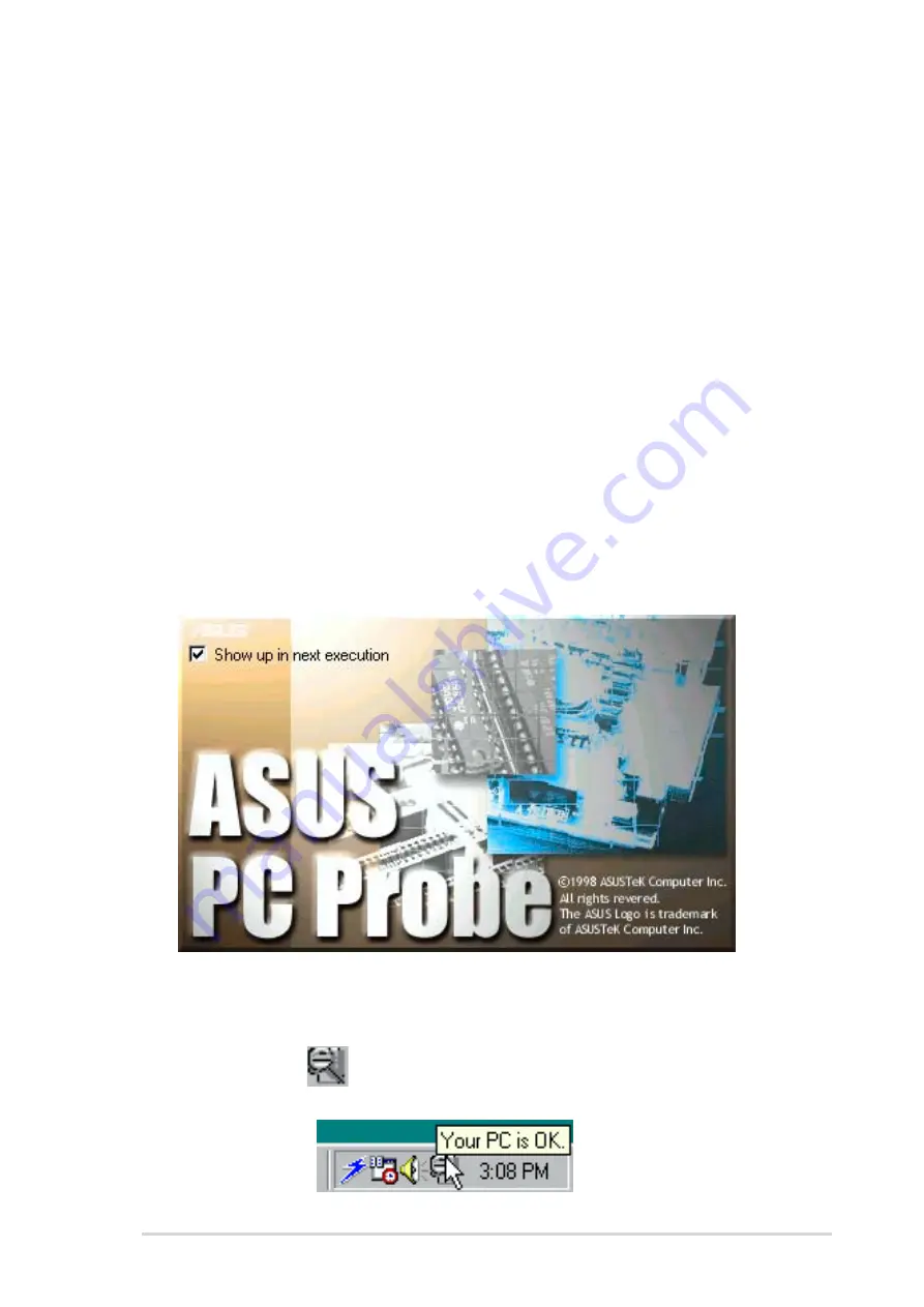
When ASUS PC Probe starts, a splash screen appears, allowing you to
select whether to show the screen again when you open PC Probe or not.
To bypass this startup screen, clear the S h o w   u p   i n   n e x t   e x e c u t i o n

S h o w   u p   i n   n e x t   e x e c u t i o n

S h o w   u p   i n   n e x t   e x e c u t i o n

S h o w   u p   i n   n e x t   e x e c u t i o n

S h o w   u p   i n   n e x t   e x e c u t i o n

check box.

To launch A S U S   P C   P r o b e

A S U S   P C   P r o b e

A S U S   P C   P r o b e

A S U S   P C   P r o b e

A S U S   P C   P r o b e, click the Windows

®

 S t a r t

S t a r t

S t a r t

S t a r t

S t a r t button, point to

P r o g r a m s

P r o g r a m s

P r o g r a m s

P r o g r a m s

P r o g r a m s, and then A S U S   U t i l i t y

A S U S   U t i l i t y

A S U S   U t i l i t y

A S U S   U t i l i t y

A S U S   U t i l i t y, and then click P r o b e   V x . x x

P r o b e   V x . x x

P r o b e   V x . x x

P r o b e   V x . x x

P r o b e   V x . x x.

3.3

Software information

Most of the applications in the support CD have wizards that will
conveniently guide you through the installation. View the online help or
readme file that came with the software for more information.

Содержание Barebone System A7VT400

Страница 1: ...Terminator 1 Barebone System Model A7VT400 ...

Страница 2: ...TIONS OF MERCHANTABILITY OR FITNESS FOR A PARTICULAR PURPOSE IN NO EVENT SHALL ASUS ITS DIRECTORS OFFICERS EMPLOYEES OR AGENTS BE LIABLE FOR ANY INDIRECT SPECIAL INCIDENTAL OR CONSEQUENTIAL DAMAGES INCLUDING DAMAGES FOR LOSS OF PROFITS LOSS OF BUSINESS LOSS OF USE OR DATA INTERRUPTION OF BUSINESS AND THE LIKE EVEN IF ASUS HAS BEEN ADVISED OF THE POSSIBILITY OF SUCH DAMAGES ARISING FROM ANY DEFECT ...

Страница 3: ...llation 2 1 Preparation 2 2 2 2 Before you proceed 2 2 2 3 Removing the cover 2 3 2 4 Detaching the drive frame 2 4 2 5 Installing a CPU 2 6 2 6 Installing the fan and heatsink assembly 2 8 2 7 Installing system memory 2 10 2 7 1 Memory configurations 2 10 2 7 2 DIMM installation 2 11 2 8 Installing an expansion card 2 12 2 8 1 Expansion slots 2 12 2 8 2 Expansion card installation 2 13 2 8 3 Conf...

Страница 4: ... 3 5 3 3 Software information 3 7 3 3 1 ASUS PC Probe 3 7 3 3 2 ASUS Update 3 11 Chapter 4 Motherboard info Chapter 4 Motherboard info Chapter 4 Motherboard info Chapter 4 Motherboard info Chapter 4 Motherboard info 4 1 Introduction 4 2 4 2 Motherboard layout 4 2 4 3 Jumpers 4 3 4 4 Connectors 4 6 Chapter 5 BIOS information Chapter 5 BIOS information Chapter 5 BIOS information Chapter 5 BIOS infor...

Страница 5: ... 5 14 5 4 2 Memory configuration 5 15 5 4 3 Chipset configuration 5 16 5 4 4 PCIPnP 5 18 5 4 5 Onboard device configuration 5 19 5 4 6 USB configuration 5 21 5 5 Power Menu 5 22 5 5 1 APM configuration 5 23 5 5 2 Hardware monitor 5 26 5 6 Boot Menu 5 28 5 6 1 Boot Device Priority 5 28 5 6 2 Removable drives 5 29 5 6 3 Hard Disk Drives 5 29 5 6 4 CD ROM drives 5 30 5 6 5 Boot settings configuration...

Страница 6: ...ry to correct the interference by one or more of the following measures Reorient or relocate the receiving antenna Increase the separation between the equipment and receiver Connect the equipment to an outlet on a circuit different from that to which the receiver is connected Consult the dealer or an experienced radio TV technician for help Canadian Department of Communications Statement Canadian ...

Страница 7: ...ay from connectors slots sockets and circuitry Avoid dust humidity and temperature extremes Do not place the product in any area where it may become wet Place the product on a stable surface If you encounter technical problems with the product contact a qualified service technician or your retailer Lithium Ion Battery Warning Lithium Ion Battery Warning Lithium Ion Battery Warning Lithium Ion Batt...

Страница 8: ...Chapter 2 Basic installation Chapter 2 Basic installation Chapter 2 Basic installation Chapter 2 Basic installation Chapter 2 Basic installation This chapter provides step by step instructions on how to install components in the system 3 3 3 3 3 Chapter 3 Starting up Chapter 3 Starting up Chapter 3 Starting up Chapter 3 Starting up Chapter 3 Starting up This chapter helps you power up the system a...

Страница 9: ...completing a task Where to find more information Where to find more information Where to find more information Where to find more information Where to find more information Refer to the following sources for additional information and for product and software updates 1 1 1 1 1 ASUS Websites ASUS Websites ASUS Websites ASUS Websites ASUS Websites The ASUS websites worldwide provide updated informat...

Страница 10: ... Terminator 1 barebone system ASUS Terminator 1 barebone system with ASUS motherboard 165 W PFC non PFC power supply unit CPU fan and heatsink assembly 2 x 5 25 drive bays 1 x 3 5 hard disk drive bay 4 x USB 2 0 ports 2 2 2 2 2 C a b l e C a b l e C a b l e C a b l e C a b l e AC power cable and plug 3 3 3 3 3 Support CD Support CD Support CD Support CD Support CD 4 4 4 4 4 User guide User guide U...

Страница 11: ...VT400 ASUS Terminator 1 A7VT400 ASUS Terminator 1 A7VT400 System introduction Chapter 1 This chapter gives a general description of the ASUS Terminator 1 A7VT400 The chapter lists the system features including introduction on the front and rear panel and internal components ...

Страница 12: ...rtainment feature The system comes in a stylish mini tower casing and is powered by the ASUS motherboard that supports AMD Sempron processors 1 1 1 1 1 Optical drive Optical drive Optical drive Optical drive Optical drive This is an optional IDE optical drive 2 2 2 2 2 Empty 5 25 inch drive bay Empty 5 25 inch drive bay Empty 5 25 inch drive bay Empty 5 25 inch drive bay Empty 5 25 inch drive bay ...

Страница 13: ...e hard disk drive 7 7 7 7 7 Front panel I O door Front panel I O door Front panel I O door Front panel I O door Front panel I O door Flip up this door to show the front panel input output ports 8 8 8 8 8 USB 2 0 ports USB 2 0 ports USB 2 0 ports USB 2 0 ports USB 2 0 ports These Universal Serial Bus 2 0 USB 2 0 ports are available for connecting USB 2 0 devices such as a mouse printer scanner came...

Страница 14: ... Serial port Serial port Serial port Serial port This port connects a mouse modem or other devices that conform with serial specification 3 3 3 3 3 PS 2 mouse port PS 2 mouse port PS 2 mouse port PS 2 mouse port PS 2 mouse port This green 6 pin connector is for a PS 2 mouse 4 4 4 4 4 PS 2 keyboard port PS 2 keyboard port PS 2 keyboard port PS 2 keyboard port PS 2 keyboard port This purple 6 pin co...

Страница 15: ...Channel 2 Channel 2 Channel Light Blue Line In Line In LFE Output Center Lime Line Out Front Speaker Out Front Speaker Out Pink Mic In Surround Surround LFE Output Low Frequency Enhanced Output LFE Output Low Frequency Enhanced Output LFE Output Low Frequency Enhanced Output LFE Output Low Frequency Enhanced Output LFE Output Low Frequency Enhanced Output Windows 98 SE only supports 4 1 channel sp...

Страница 16: ...the drive frame The standard components already installed in the system and the locations of the available drive bays are pointed out The system may come with either a PFC Power Factor Correction or non PFC power supply 4 3 5 HDD drive bay 5 3 5 floppy drive bay Optional floppy disk drive 6 PFC Non PFC power supply 7 USB audio board 1 Game MIDI COM1 extension module 2 Motherboard 3 Two 5 25 drive ...

Страница 17: ...US Terminator 1 A7VT400 ASUS Terminator 1 A7VT400 ASUS Terminator 1 A7VT400 ASUS Terminator 1 A7VT400 This chapter gives step by step instructions on how to install components into the barebone system Basic installation Chapter 2 ...

Страница 18: ...rap or touch a safely grounded object or a metal object such as the power supply case before handling components to avoid damaging them due to static electricity Hold components by the edges to avoid touching the ICs on them Whenever you uninstall any component place it on a grounded antistatic pad or in the bag that came with the component Before you proceed make sure that you have all the compon...

Страница 19: ...crew aside 2 Place your hands on both corners of the front panel just beside the CD ROM frame Push on the CD ROM area with your thumbs until the cover tilts forward 3 While supporting the front panel with one hand place your other hand on the top rear edge of the cover and carefully lift the cover from the chassis Screw T I P T I P T I P T I P T I P Another way to release the cover is to place you...

Страница 20: ... 1 Place the chassis on a flat surface and turn it on its side 2 The power socket and voltage selector switch are attached to a metal module secured to the rear panel by a screw Remove the screw to release the power socket module P o w e r P o w e r P o w e r P o w e r P o w e r s o c k e t s o c k e t s o c k e t s o c k e t s o c k e t m o d u l e m o d u l e m o d u l e m o d u l e m o d u l e ...

Страница 21: ...it is completely detached from the rear panel 4 Unlatch the drive frame by pulling it outward The drive frame has a swivel hinge like edge that is attached to the main chassis You do not have to completely detach the drive frame from the chassis when installing components 5 Carefully lay the drive frame alongside the main chassis frame Drive frame Drive frame Drive frame Drive frame Drive frame Sw...

Страница 22: ... the AMD Sempron processor Take note of the marked corner with gold triangle on the CPU This mark should match a specific corner on the socket to ensure correct installation G o l d G o l d G o l d G o l d G o l d triangle triangle triangle triangle triangle CPU installation CPU installation CPU installation CPU installation CPU installation To install the CPU 1 Locate the 462 pin ZIF socket on th...

Страница 23: ...a 90 100 angle Make sure that the socket lever is lifted up to a 90 100 angle otherwise the CPU does not fit in completely The CPU fits only in one correct orientation DO NOT force the CPU into the socket to prevent bending the pins and damaging the CPU 5 When the CPU is in place push down the socket lever to secure the CPU The lever clicks on the side tab to indicate that it is locked Gold triang...

Страница 24: ... installed CPU such that the heatsink fins are perpendicular to the DDR sockets and PCI slots 2 Align one end of the heatsink bracket to the protruding tabs on the CPU socket Hook the holes of the bracket to the protruding tabs making sure that they fit properly Socket tabs Socket tabs Socket tabs Socket tabs Socket tabs Heatsink bracket Heatsink bracket Heatsink bracket Heatsink bracket Heatsink ...

Страница 25: ...ator 1 A7VT400 ASUS Terminator 1 A7VT400 ASUS Terminator 1 A7VT400 4 Connect the CPU fan cable from the assembly to the fan connector labeled CPU_FAN1 CPU fan connector CPU fan connector CPU fan connector CPU fan connector CPU fan connector CPU_FAN1 CPU_FAN1 CPU_FAN1 CPU_FAN1 CPU_FAN1 ...

Страница 26: ...F S B C P U F S B C P U F S B C P U F S B DDR DIMM Type DDR DIMM Type DDR DIMM Type DDR DIMM Type DDR DIMM Type Memory Frequency Memory Frequency Memory Frequency Memory Frequency Memory Frequency 100 MHz PC2100 PC1600 266 200 MHz 133MHz PC2700 PC2100 PC1600 333 266 200 MHz 166 MHz PC2700 PC2100 PC1600 333 266 200 MHz 200 MHz PC2700 PC2100 PC1600 333 266 200 MHz When using 100 MHz CPU FSB any DDR ...

Страница 27: ...t 4 Firmly insert the DIMM into the socket until the retaining clips snap back in place and the DIMM is properly seated A DDR DIMM is keyed with a notch so that it fits in only one direction DO NOT force a DIMM into a socket to avoid damaging the DIMM Socket break Socket break Socket break Socket break Socket break DIMM notch DIMM notch DIMM notch DIMM notch DIMM notch DDR DIMM sockets DDR DIMM so...

Страница 28: ... AGP cards The motherboard does not support 3 3V AGP cards Make sure to unplug the power cord before adding or removing expansion cards Failure to do so may cause you physical injury and damage the motherboard 2 8 1 2 8 1 2 8 1 2 8 1 2 8 1 Expansion slots Expansion slots Expansion slots Expansion slots Expansion slots PCI slot PCI slot PCI slot PCI slot PCI slot The PCI slot supports PCI slots suc...

Страница 29: ...I1 PCI slot PCI1 Metal bracket Metal bracket Metal bracket Metal bracket Metal bracket 2 8 2 2 8 2 2 8 2 2 8 2 2 8 2 Expansion card installation Expansion card installation Expansion card installation Expansion card installation Expansion card installation 2 8 3 2 8 3 2 8 3 2 8 3 2 8 3 Configuring an expansion card Configuring an expansion card Configuring an expansion card Configuring an expansio...

Страница 30: ...sk Controller 7 15 Printer Port LPT1 8 3 System CMOS Real Time Clock 9 4 ACPI Mode when used 10 5 Multimedia Device 11 6 Network Controller 12 7 PS 2 Compatible Mouse Port 13 8 Numeric Data Processor 14 9 Primary IDE Channel 15 10 Secondary IDE Channel These IRQs are usually available for ISA or PCI devices These IRQs are usually available for ISA or PCI devices These IRQs are usually available fo...

Страница 31: ...ou acquired a model without a CD ROM To install a CD ROM drive 1 Place the chassis upright 2 Insert the CD ROM drive into the upper 5 25 inch drive bay CD ROM screws CD ROM screws CD ROM screws CD ROM screws CD ROM screws 5 25 inch drive bay 5 25 inch drive bay 5 25 inch drive bay 5 25 inch drive bay 5 25 inch drive bay 3 Carefully push the CD ROM drive into the bay until its screw holes align wit...

Страница 32: ...d stripe to Pin 1 Red stripe to Pin 1 Red stripe to Pin 1 IDE ribbon cable IDE ribbon cable IDE ribbon cable IDE ribbon cable IDE ribbon cable Power cable P1 Power cable P1 Power cable P1 Power cable P1 Power cable P1 CD ROM audio cable CD ROM audio cable CD ROM audio cable CD ROM audio cable CD ROM audio cable 9 Connect the other end of the audio cable to the black 4 pin connector labeled CD on t...

Страница 33: ...nch HDD drive bay 3 5 inch HDD drive bay 3 5 inch HDD drive bay 3 5 inch HDD drive bay 3 5 inch HDD drive bay Internal view Internal view Internal view Internal view Internal view External view External view External view External view External view To install an IDE HDD 1 Place the chassis upright 2 With the HDD label side up carefully insert the drive into the 3 5 inch bay HDD label side HDD lab...

Страница 34: ...D matching the red stripe on the cable with Pin 1 on the IDE interface Red stripe to Pin 1 Red stripe to Pin 1 Red stripe to Pin 1 Red stripe to Pin 1 Red stripe to Pin 1 IDE ribbon cable IDE ribbon cable IDE ribbon cable IDE ribbon cable IDE ribbon cable Power cable P3 Power cable P3 Power cable P3 Power cable P3 Power cable P3 7 Connect the other end of the IDE ribbon cable to the primary IDE co...

Страница 35: ...r switch power switch power switch power switch power switch and power LED power LED power LED power LED power LED cables to their respective leads in the PANEL connector on the motherboard Connect the HDD LED HDD LED HDD LED HDD LED HDD LED cable to the 2 pin lead marked HDLED Power switch Power switch Power switch Power switch Power switch Power LED Power LED Power LED Power LED Power LED HDD LE...

Страница 36: ...SB34 connector Connect to USB34 connector Connect to USB34 connector Connect to USB34 connector on the motherboard on the motherboard on the motherboard on the motherboard on the motherboard Connect to MIC_LOUT Connect to MIC_LOUT Connect to MIC_LOUT Connect to MIC_LOUT Connect to MIC_LOUT connector on the connector on the connector on the connector on the connector on the motherboard motherboard ...

Страница 37: ...w ready to put the system back together To re assemble the system 1 With the chassis lying on its side hook the swivel edge of the drive frame to the main chassis 2 Sway the drive frame inward until it fits completely The protruding tabs on both ends of the drive frame should snap perfectly to the chassis edge Protruding tab Protruding tab Protruding tab Protruding tab Protruding tab 3 Turn the ch...

Страница 38: ...s 6 Push the cover towards the rear until it fits The locking tab snaps into the hole on the chassis indicating that the cover is in place Locking tab hole Locking tab hole Locking tab hole Locking tab hole Locking tab hole Locking tab Locking tab Locking tab Locking tab Locking tab Firmly push the cover to ensure that it is fully engaged to the chassis 7 Lock the cover with the screw on the rear ...

Страница 39: ...l S e r i a l S e r i a l VGA VGA VGA VGA VGA M i c M i c M i c M i c M i c G a m e G a m e G a m e G a m e G a m e M I D I M I D I M I D I M I D I M I D I P S 2 P S 2 P S 2 P S 2 P S 2 M o u s e M o u s e M o u s e M o u s e M o u s e A C A C A C A C A C Parallel Parallel Parallel Parallel Parallel USB USB USB USB USB R J 4 5 R J 4 5 R J 4 5 R J 4 5 R J 4 5 PS 2 PS 2 PS 2 PS 2 PS 2 K B K B K B K ...

Страница 40: ...t Maximum Input ac Current Maximum Input ac Current Maximum Input ac Current 4 A max at 115 Vac 2 A max at 230 Vac maximum load Inrush Current Inrush Current Inrush Current Inrush Current Inrush Current 90 A max at 115 Vac full load cold start at 25 C Efficiency Efficiency Efficiency Efficiency Efficiency 70 min at nominal input maximum load O u t p u t O u t p u t O u t p u t O u t p u t O u t p ...

Страница 41: ...S Terminator 1 A7VT400 ASUS Terminator 1 A7VT400 ASUS Terminator 1 A7VT400 ASUS Terminator 1 A7VT400 This chapter helps you power up your system and install drivers and utilities that came with the support CD Starting up Chapter 3 ...

Страница 42: ...ROM drive If Autorun is enabled in your computer the Utilities menu automatically appears on your screen Because motherboard settings and hardware options vary use the setup procedures presented in this chapter for general reference only Refer to your OS documentation for more information Click an item to install Click an item to install Click an item to install Click an item to install Click an i...

Страница 43: ...or this motherboard Simply click on a specific item then follow the installation wizard to install it ASUS PC Probe ASUS PC Probe ASUS PC Probe ASUS PC Probe ASUS PC Probe This smart utility monitors the fan speed CPU temperature and system voltages and alerts you of any detected problems This utility helps you keep your computer at a healthy operating condition ASUS Update ASUS Update ASUS Update...

Страница 44: ...pplication Anti virus application Anti virus application Anti virus application Anti virus application The anti virus application scans identifies and removes computer viruses View the online help for detailed information ADOBE Acrobat Reader ADOBE Acrobat Reader ADOBE Acrobat Reader ADOBE Acrobat Reader ADOBE Acrobat Reader This item installs the Adobe Acrobat Reader The Acrobat Reader software i...

Страница 45: ...on The icons on the top right of the screen give additional information on the motherboard and the contents of the support CD Click an icon to display the specified information Motherboard Info Motherboard Info Motherboard Info Motherboard Info Motherboard Info Displays the general specifications of the motherboard The screen image below is for general reference only The support CD will automatica...

Страница 46: ... support form Technical support form Displays the ASUS Technical Support Request Form that you have to fill out when requesting technical support Filelist Filelist Filelist Filelist Filelist Displays the contents of the support CD and a brief description of each in text format Browse this CD Browse this CD Browse this CD Browse this CD Browse this CD Displays the support CD contents in graphical f...

Страница 47: ...obe Starting ASUS PC Probe Starting ASUS PC Probe Starting ASUS PC Probe Starting ASUS PC Probe When ASUS PC Probe starts a splash screen appears allowing you to select whether to show the screen again when you open PC Probe or not To bypass this startup screen clear the Show up in next execution Show up in next execution Show up in next execution Show up in next execution Show up in next executio...

Страница 48: ...erature Warning Temperature Warning Temperature Warning Temperature Warning Temperature Warning threshold adjustment threshold adjustment threshold adjustment threshold adjustment threshold adjustment Move the slider up to increase the threshold level or down to decrease the threshold level Fan Monitor Fan Monitor Fan Monitor Fan Monitor Fan Monitor Shows the PC fan rotation Voltage Monitor Voltag...

Страница 49: ...hows the used and free space of the PC s hard disk drives and the file allocation table or file system used Fan Control Fan Control Fan Control Fan Control Fan Control Lets you enable disable Smart Fan Control Smart Fan Control adjusts the fan speed automatically based on the current CPU temperature and predefined threshold CPU Cooling System Setup CPU Cooling System Setup CPU Cooling System Setup...

Страница 50: ... Explorer DMI Explorer DMI Explorer Shows information pertinent to the PC such as CPU type CPU speed and internal external frequencies and memory size Utility Utility Utility Utility Utility Lets you run programs outside of the ASUS Probe modules To run a program click Execute Program Execute Program Execute Program Execute Program Execute Program Memory Memory Memory Memory Memory Shows the PC me...

Страница 51: ...C Probe Task Bar Icon ASUS PC Probe Task Bar Icon ASUS PC Probe Task Bar Icon ASUS PC Probe Task Bar Icon ASUS PC Probe Task Bar Icon Right clicking the PC Probe icon brings up a menu to open or exit ASUS PC Probe and pause or resume all system monitoring When the ASUS PC Probe senses a problem with your PC portions of the ASUS PC Probe icon change to red the PC speaker beeps and the ASUS PC Probe...

Страница 52: ...affic or choose Auto Select Click Next Next Next Next Next 4 From the FTP site select the BIOS version that you wish to download Click Next Next Next Next Next 5 Follow the instructions on the succeeding screens to complete the update process If you selected the option to update the BIOS from a file a window pops up prompting you to locate the file Select the file click Save then follow the screen...

Страница 53: ...minator T1 A7VT400 ASUS Terminator T1 A7VT400 ASUS Terminator T1 A7VT400 This chapter gives information about the motherboard that came with the system This chapter includes the motherboard layout jumper settings and connector locations Motherboard info Chapter 4 ...

Страница 54: ...tion about the motherboard for future upgrades or system reconfiguraiton 4 2 Motherboard layout 23cm 9 06in CPU_FAN VIA KM400A CHA_FAN FLOPPY AD1888 PANEL USB34 USBPWR12 IOC_MB DDR DIMM2 64 72 bit 184 pin module PCI1 Super I O Flash BIOS 22 4cm 8 82in PS 2 T Mouse B Keyboard RJ 45 USB T Port2 B Port1 DDR DIMM1 64 72 bit 184 pin module PRI_IDE ATX12V LANLED BUZZER VIA VT8235M Socket 462 CLRTC SEC_I...

Страница 55: ...onnected USB devices Set to 5VSB to wake up from S3 S4 and S5 sleep mode no power to CPU DRAM in slow refresh power supply in reduced power mode The USBPWR12 jumper is for the rear USB ports The USBPWR34 and USBPWR56 jumpers are for the internal USB connectors that you can connect to additional USB ports The motherboard provides 0 5A for each USB port and 1 5A for all devices requiring 5VSB power ...

Страница 56: ...sing the CMOS RTC RAM data The onboard button cell battery powers the RAM data in CMOS which include system setup information such as system passwords To erase the RTC RAM 1 Turn OFF the computer and unplug the power cord 2 Remove the battery 3 Move the jumper cap from pins 2 3 default to pins 1 2 Keep the cap on pins 1 2 for about 5 10 seconds then move the cap back to pins 2 3 4 Re install the b...

Страница 57: ...B External frequency selection FSB External frequency selection FSB External frequency selection FSB External frequency selection FSB This jumper allows you to set the CPU Front Side Bus FSB frequency Set the jumper to 2 3 only when your CPU FSB frequency is 100 MHz If your CPU FSB frequency is 133 166 200 MHz set the jumper to 1 2 External frequency selection 100 Default 133 166 200 FSB 1 2 2 3 ...

Страница 58: ...MA 133 100 66 signal cable has three connectors a blue connector for the primary IDE connector on the motherboard a black connector for an Ultra DMA 133 100 66 IDE slave device optical drive hard disk drive and a gray connector for an Ultra DMA 133 100 66 IDE master device hard disk drive If you install two hard disk drives you must configure the second drive as a slave device by setting its jumpe...

Страница 59: ...onnect the other end to the floppy drive Pin 5 is removed to prevent incorrect insertion when using ribbon cables with pin 5 plug 3 3 3 3 3 Internal audio connectors 4 pin AUX CD Internal audio connectors 4 pin AUX CD Internal audio connectors 4 pin AUX CD Internal audio connectors 4 pin AUX CD Internal audio connectors 4 pin AUX CD These connectors allow you to receive stereo audio input from sou...

Страница 60: ... firmly until the connectors completely fit Make sure to connect the 4 pin ATX 12V power plug otherwise the system does not boot up 5 5 5 5 5 Front panel audio connector 5 1 pin MIC_LOUT Front panel audio connector 5 1 pin MIC_LOUT Front panel audio connector 5 1 pin MIC_LOUT Front panel audio connector 5 1 pin MIC_LOUT Front panel audio connector 5 1 pin MIC_LOUT This connector is for a chassis m...

Страница 61: ...upport cooling fans of 350mA 740mA 8 88W max or a total of 1A 2 22A 26 64W max at 12V Connect the fan cables to the fan connectors on the motherboard making sure that the black wire of each cable matches the ground pin of the connector Do not forget to connect the fan cables to the fan connectors Insufficient air flow inside the system may damage the motherboard components These are not jumpers Do...

Страница 62: ...34 USB56 USB 2 0 connectors 10 1 pin USB34 USB56 USB 2 0 connectors 10 1 pin USB34 USB56 USB 2 0 connectors 10 1 pin USB34 USB56 These connectors are for USB 2 0 ports Connect the USB module cable to any of these connectors then install the module to a slot opening at the back of the system chassis These USB connectors comply with USB 2 0 specification that supports up to 480 Mbps connection speed...

Страница 63: ...ty LED cable to this connector The IDE LED lights up or flashes when data is read from or written to the HDD System management interrupt 2 pin SMI System management interrupt 2 pin SMI System management interrupt 2 pin SMI System management interrupt 2 pin SMI System management interrupt 2 pin SMI This 2 pin connector allows you to manually place the system in suspend mode or green mode where syst...

Страница 64: ...4 12 4 12 4 12 4 12 4 12 Chapter 4 Motherboard information Chapter 4 Motherboard information Chapter 4 Motherboard information Chapter 4 Motherboard information Chapter 4 Motherboard information ...

Страница 65: ...7VT400 ASUS Terminator 1 A7VT400 ASUS Terminator 1 A7VT400 ASUS Terminator 1 A7VT400 This chapter tells how to change system settings through the BIOS Setup menus It includes detailed descriptions of the BIOS parameters BIOS information Chapter 5 ...

Страница 66: ...ate Disk Create Disk Create Disk Create Disk button d Insert a 1 44 MB floppy disk when prompted Follow the succeeding screen instructions to complete the process Important notes Important notes Important notes Important notes Important notes Save a copy of the original motherboard BIOS file original motherboard BIOS file original motherboard BIOS file original motherboard BIOS file original mothe...

Страница 67: ... BIOS to the bootable floppy disk 5 1 2 5 1 2 5 1 2 5 1 2 5 1 2 Updating the BIOS using the AwardBIOS Updating the BIOS using the AwardBIOS Updating the BIOS using the AwardBIOS Updating the BIOS using the AwardBIOS Updating the BIOS using the AwardBIOS Flash Utility Flash Utility Flash Utility Flash Utility Flash Utility The Basic Input Output System BIOS can be updated using the built in Flash M...

Страница 68: ...6LYA0AC DATE 12 07 2004 Flash Type SST 39SF020 5V File Name to Program 6 Type the BIOS file name in the File Name to File Name to File Name to File Name to File Name to Program Program Program Program Program field then press Enter 7 The utility prompts you to save the current BIOS file Press Y to save the current BIOS file to the floppy disk or N to continue If you intend to save the current BIOS...

Страница 69: ...hing Memory OFE00 OK Write OK No Update Write Fail 123 123 123 123 1234567890123456789012345678901 1234567890123456789012345678901 1234567890123456789012345678901 123 123 123 123 123 123 123 123 9 The utility displays a Flashing Complete Flashing Complete Flashing Complete Flashing Complete Flashing Complete message indicating that you have successfully flashed the BIOS file Remove the floppy disk...

Страница 70: ... have saved a copy of the original motherboard BIOS to a bootable floppy disk you may also use this disk to restore the BIOS To recover the BIOS from a floppy disk To recover the BIOS from a floppy disk To recover the BIOS from a floppy disk To recover the BIOS from a floppy disk To recover the BIOS from a floppy disk 1 Boot the system 2 When a corrupted BIOS is detected the following message appe...

Страница 71: ...te ASUS Update ASUS Update The ASUS Update is a utility that allows you to update the motherboard BIOS in Windows environment This utility is available in the support CD that comes with the motherboard package ASUS Update requires an Internet connection either through a network or an Internet Service Provider ISP Go to section 3 3 2 ASUS Update for details on how to update the motherboard BIOS usi...

Страница 72: ...p program so that the computer can recognize these changes and record them in the CMOS RAM of the Flash ROM The Flash ROM on the motherboard stores the Setup utility When you start up the computer the system provides you with the opportunity to run this program Press Delete during the Power On Self Test POST to enter the Setup utility otherwise POST continues with its test routines To enter Setup ...

Страница 73: ...th their corresponding functions Navigation Key s Navigation Key s Navigation Key s Navigation Key s Navigation Key s Function Description Function Description Function Description Function Description Function Description F1 or Alt H F1 or Alt H F1 or Alt H F1 or Alt H F1 or Alt H Displays the General Help screen from anywhere in the BIOS Setup E s c E s c E s c E s c E s c Jumps to the Exit menu...

Страница 74: ...me to display the first page press End to go to the last page To exit the help window press Enter or Esc Sub menu Sub menu Sub menu Sub menu Sub menu Note that a right pointer symbol as shown on the left appears to the left of certain fields This pointer indicates that you can display a sub menu from this field A sub menu contains additional options for a field parameter To display a sub menu move...

Страница 75: ...Month 1 to 12 Day 1 to 31 Year up to 2084 Use the Tab key to move between the month day and year fields 5 3 3 5 3 3 5 3 3 5 3 3 5 3 3 Legacy Diskette A 1 44M 3 5 in Legacy Diskette A 1 44M 3 5 in Legacy Diskette A 1 44M 3 5 in Legacy Diskette A 1 44M 3 5 in Legacy Diskette A 1 44M 3 5 in Sets the type of floppy drive installed Configuration options Disabled 360K 5 25 in 1 2M 5 25 in 720K 3 5 in 1 ...

Страница 76: ...tect incorrect parameters In these cases select Manual to manually enter the IDE hard disk drive parameters Refer to the next section for details Before attempting to configure a hard disk drive make sure you have the correct configuration information supplied by the drive manufacturer Incorrect settings may cause the system to fail to recognize the installed hard disk Primary IDE Master Auto Acce...

Страница 77: ... and data integrity for compatible IDE devices Set to Disabled to suppress Ultra DMA capability 5 4 Advanced Menu CPU Configuration Memory Configuration Chipset PCIPnP Onboard Device Configuration USB Configuration Select Menu Item Specific Help Press Enter to Set The Advanced menu items allow you to change the settings for the CPU and other system devices Take caution when changing the settings o...

Страница 78: ...information 5 4 1 5 4 1 5 4 1 5 4 1 5 4 1 CPU configuration CPU configuration CPU configuration CPU configuration CPU configuration The items in this menu show the CPU related information auto detected by the BIOS CPU Type AMD Athlon tm CPU Speed 1000 MHz Cache RAM 256 K Current FSB Frequency 100 MHz Select Menu Item Specific Help CPU Configuration ...

Страница 79: ...elect Safe to set the DRAM timing to safe value Configuration options Auto by SPD Manual Safe DRAM Burst Length 4 DRAM Burst Length 4 DRAM Burst Length 4 DRAM Burst Length 4 DRAM Burst Length 4 Sets the DRAM burst length width Configuration options 4 8 DRAM Command Rate 2T Command DRAM Command Rate 2T Command DRAM Command Rate 2T Command DRAM Command Rate 2T Command DRAM Command Rate 2T Command Se...

Страница 80: ...t Onchip AGP to boot from the Onboard VGA even if there is an AGP card Configuration options Auto Onchip AGP Init Display First PCI slot Init Display First PCI slot Init Display First PCI slot Init Display First PCI slot Init Display First PCI slot Allows you to set which graphics controller to use as the primary boot device Configuration options PCI slot AGP AGP Bridge Configuration AGP Bridge Co...

Страница 81: ...e using an AGP 8X card Configuration options 1X 2X 4X 8X AGP Fast Write Disabled This item allows you to enable or disable the AGP fast write feature The AGP fast write is a data transfer protocol that combines PCI and AGP protocols to support continuous data transfer directly from the chipset to the AGP Configuration options Disabled Enabled Onboard Video Memory 32M This item allows you to set th...

Страница 82: ...en press Enter to display a pop up menu with the configuration options Plug Play O S No Resources Controlled By Auto x IRQ Resources PCI VGA Palette Snoop Disabled Assign IRQ for VGA Enabled Select Menu Item Specific Help PCIPnP When the item Resources Controlled By Resources Controlled By Resources Controlled By Resources Controlled By Resources Controlled By is set to Auto the item IRQ Resources...

Страница 83: ...d Onboard LAN Enabled Allows you to enable or disable the onboard LAN controller Keep the default enabled if you wish to use the onboard LAN feature Set to Disabled if you installed a PCI LAN card Configuration options Disabled Enabled Serial Port1 Address 3F8 IRQ4 Serial Port1 Address 3F8 IRQ4 Serial Port1 Address 3F8 IRQ4 Serial Port1 Address 3F8 IRQ4 Serial Port1 Address 3F8 IRQ4 Allows you to ...

Страница 84: ... Port Mode Parallel Port Mode Parallel Port Mode is set to EPP or ECP EPP Configuration options EPP1 7 EPP1 9 ECP Mode Use DMA 3 ECP Mode Use DMA 3 ECP Mode Use DMA 3 ECP Mode Use DMA 3 ECP Mode Use DMA 3 Allows you to select the ECP Mode This item becomes configurable only if the Parallel Port Mode Parallel Port Mode Parallel Port Mode Parallel Port Mode Parallel Port Mode is set to ECP or ECP EP...

Страница 85: ...led USB 1 1 Controller Enabled USB 1 1 Controller Enabled USB 1 1 Controller Enabled USB 1 1 Controller Enabled Allows you to enable or disable the USB 1 1 controller Configuration options Enabled Disabled USB 2 0 Controller Enabled USB 2 0 Controller Enabled USB 2 0 Controller Enabled USB 2 0 Controller Enabled USB 2 0 Controller Enabled Allows you to enable or disable the EHCI controller Setting...

Страница 86: ... ACPI Suspend Type S1 S3 ACPI Suspend Type S1 S3 ACPI Suspend Type S1 S3 ACPI Suspend Type S1 S3 Allows you to select the ACPI state used for system suspend Configuration options S1 POS S3 STR S1 S3 ACPI APIC Support Enabled ACPI APIC Support Enabled ACPI APIC Support Enabled ACPI APIC Support Enabled ACPI APIC Support Enabled Allows you enable or disable the ACPI feature on the operating system C...

Страница 87: ...ion options Hot key Password PS2KB Wakeup from S3 S4 S5 Disabled PS2KB Wakeup from S3 S4 S5 Disabled PS2KB Wakeup from S3 S4 S5 Disabled PS2KB Wakeup from S3 S4 S5 Disabled PS2KB Wakeup from S3 S4 S5 Disabled Allows you to use specific keys on the keyboard to turn on the system This feature requires an ATX power supply that provides at least 1A on the 5VSB lead Configuration options Disabled Ctrl ...

Страница 88: ... item is enabled you can set the date and time of alarm using the two following items Configuration options Disabled Enabled Date of Month 0 Date of Month 0 Date of Month 0 Date of Month 0 Date of Month 0 To set the date of alarm highlight this item and press Enter to display a pop up menu Key in a value within the specified range then press Enter Configuration options Min 0 Max 31 Resume time hh ...

Страница 89: ...han 4 seconds When set to Suspend press the power button for more more more more more than 4 seconds to power off the system Configuration options Suspend Instant Off Restore on AC Power Loss Power Off Restore on AC Power Loss Power Off Restore on AC Power Loss Power Off Restore on AC Power Loss Power Off Restore on AC Power Loss Power Off Allows you to set whether or not to reboot the system afte...

Страница 90: ...ature xxx CPU Temperature xxx CPU Temperature xxx CPU Temperature xxx CPU Temperature xxxo o o o o C xxx C xxx C xxx C xxx C xxxo o o o o F F F F F The onboard hardware monitor automatically detects and displays the power supply and CPU temperatures in these fields Chassis Fan Speed xxxxRPM Chassis Fan Speed xxxxRPM Chassis Fan Speed xxxxRPM Chassis Fan Speed xxxxRPM Chassis Fan Speed xxxxRPM CPU ...

Страница 91: ...CORE Voltage 3 3V Voltage 5V Voltage VCORE Voltage 3 3V Voltage 5V Voltage VCORE Voltage 3 3V Voltage 5V Voltage VCORE Voltage 3 3V Voltage 5V Voltage VCORE Voltage 3 3V Voltage 5V Voltage 12V Voltage 12V Voltage 12V Voltage 12V Voltage 12V Voltage The onboard hardware monitor automatically detects the voltage output through the onboard voltage regulators ...

Страница 92: ... menu with the configuration options Boot Device Priority Removable Drives Hard Drisk Drives CDROM Drives Boot Settings Configuration Security Select Menu Item Specific Help 5 6 1 5 6 1 5 6 1 5 6 1 5 6 1 Boot device priority Boot device priority Boot device priority Boot device priority Boot device priority Select Menu Item Specific Help Select your Boot Device Priority 1st Boot Device Removable 2...

Страница 93: ...evice Disabled 4th Boot Device Disabled 4th Boot Device Disabled These items allow you to select your boot device priority Configuration options Removable Hard Disk CDROM Disabled 5 6 2 5 6 2 5 6 2 5 6 2 5 6 2 Removable drives Removable drives Removable drives Removable drives Removable drives Removable Drives 1 Floppy Disks Item Specific Help Use up or down arrow to select a device then press to ...

Страница 94: ...ettings configuration Boot settings configuration Boot settings configuration Boot settings configuration Boot Settings COnfiguration Quick Boot Enabled Boot Up Floppy Seek Disabled Boot Num Lock On Typematic Rate Setting Disabled x Typematic Rate Chars Sec 6 x Typematic Delay Msec 250 OS Select for DRAM 64MB Non OS2 Halt On All Errors Item Specific Help Allows the system to skip certain tests whi...

Страница 95: ...Sec Typematic Rate Chars Sec Typematic Rate Chars Sec and Typematic Delay Typematic Delay Typematic Delay Typematic Delay Typematic Delay become configurable only when the item Typematic Setting is enabled Typematic Rate Chars Sec 6 Typematic Rate Chars Sec 6 Typematic Rate Chars Sec 6 Typematic Rate Chars Sec 6 Typematic Rate Chars Sec 6 Allows you to select the rate at which character repeats wh...

Страница 96: ...e exact characters again then press Enter The password field setting is changed to Set 5 6 6 5 6 6 5 6 6 5 6 6 5 6 6 Security Security Security Security Security Security Supervisor Password Clear User Password Clear Password Check Setup Item Specific Help Supervisor password controls full access Enter to change password Select Menu To clear the password 1 Highlight the password field and press En...

Страница 97: ...the BIOS setup or the system Select Setup to require the password before entering the BIOS Setup Select System to require the password before entering the system Configuration options Setup System 5 7 Exit menu The Exit menu items allow you to load the BIOS setup default settings save or discard any changes you made or exit the Setup utility Exit Save Changes Exit Discard Changes Load Setup Defaul...

Страница 98: ...tup Defaults Load Setup Defaults Load Setup Defaults Load Setup Defaults Load Setup Defaults This option allows you to load the default values for each of the parameters on the Setup menus When you select this option or if you press F5 a confirmation window appears Select Yes to load default values Select Exit Saving Changes or make other changes before saving the values to the non volatile RAM Di...

Отзывы: