


Chapter 2: Hardware setup
2-16
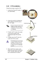
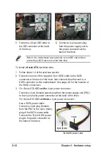
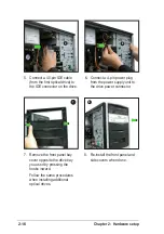
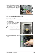
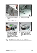
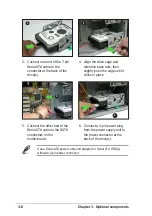
5. Connect a 40-pin IDE cable
(from the first optical drive) to
the IDE connector on the drive.
6. Connect a 4-pin power plug
from the power supply unit to
the drive power connector.
6
5
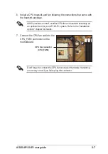
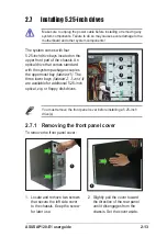
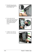
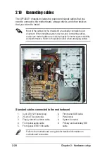
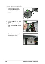
7. Remove the front panel bay
cover opposite the drive bay
you used by pressing the
hooks inward.
Follow the same procedures
when installing additional
optical drives.
8
7
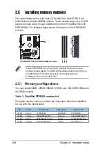
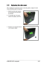
8. Re-install the front panel and
side covers when done.
Содержание AP120-E1
Страница 1: ...P4 Pedestal Server Workstation 800MHz Front Side Bus User Guide AP120 E1 ...
Страница 38: ...Chapter 2 Hardware setup 2 22 ...
Страница 48: ...Chapter 3 Optional components 3 10 ...