Step 19:
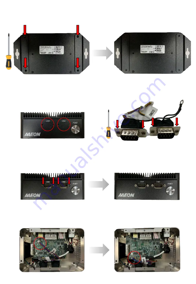
Line up the COM ports with the correct holes. Check the attached labels to ensure the ports are
mounted to the matching labeled I/O hole. Secure with retainer screws.
Step 20:
Attach the grounding wire to the closest board mounting screw as shown. Connect the cable to the
COM Port 1/Port 2 connector (CN2).
Step 18:
Dual COM Port installation (optional). Remove I/O punchouts from front of system. Remove the retainer
screws from each port connector, four in total.
Step 17:
Wall Mount (Requires wall mount bracket kit). Line up brackets with the four holes shown. Secure with
four black screws. System can now be mounted to wall or surface.


