Astronergy CHSM60M-HC Скачать руководство пользователя страница 2


Chint Solar (Zhejiang) Co., Ltd. | Add:1335 Bin´an Road, Binjiang District, Hangzhou | P.C: 310053 
Tel: 0086-571-5603 1888 | Fax: 086-571-5603 2316 | Website: http://energy.chint.com/


1.  Introduction 

1.1 Purpose 

This  document  provides  detailed  instructions  and  valuable  safety  information  regarding  the 

installation, electrical connection, and maintenance of following Chint Solar Crystalline Photovoltaic 
modules: 

CHSM6610M 


CHSM6610M(BL)   

CHSM6610M/HV  CHSM60M-HC 

CHSM60M(BL)-HC  CHSM6610P   


CHSM6610P/HV  CHSM60P-HC 

CHSM6612M 


CHSM6612M/HV   

CHSM72M-HC 

CHSM6612P 


CHSM6612P/HV   

CHSM72P-HC 

All the instructions should be read and understood before installation. The installers should 

be trained and conform to all safety precautions in this guide when installing the module. Keep 
this guide in a safe place for further reference. 

1.2 Limitation of Liability 

Because the use of this manual and the conditions or methods of installation, operation, use 

and maintenance of photovoltaic  (PV)  products  are beyond  Chint  Solar’s  control,  Chint Solar 
does not afford the responsibility and expressly disclaims liability for loss, damage, or expense 
arising  out  of  or  in  any  way  connected  with  such  installation,  operation,  use  or maintenance. 
Chint Solar reserves the right to change the manual without prior notice. 

1.3 Precautions of Installation 

1.3.1 Module’s unpack and transfer 

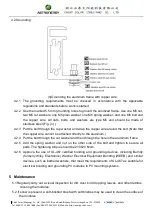
a)  When the whole pallet of modules are delivered to the site and unloaded, make sure the 

safety of the module especially if they need to be lifted for roof projects. Put them into a 

protective device and then lift it to the roof in case of bumping against the wall during the 

lifting process. 

b)  Firstly, tear the stretch film, then move away the top cover after cutting off each module 

packing strip while unpacking. Two operators work as a group, grasp the module frame 

tightly in the same direction and take out the module one by one. It is a must that the 

operators remove the adhesive tape of the fixed module one by one, rive one piece and 

then take out one piece of module. We don’t allow tearing off all the adhesive tape at one 

time to prevent the whole package from toppling over or falling down. The whole process 

must be taken very gently. Don’t collide with any hard object or let any parts of the frame 

Содержание CHSM60M-HC

Страница 1: ...int com Crystalline Silicon PV Module Installation Manual 1 Introduction 1 1 Purpose 1 2 Limitation of Liability 1 3 Precautions for Installation 2 Safety 2 1 General Safety 2 2 Installation Safety 3 Mechanical Installation 3 1 Installation Condition 3 2 Installation Methods 4 Electrical Installation 4 1 Installation Condition 4 2 Grounding 5 Maintenance ...

Страница 2: ...the responsibility and expressly disclaims liability for loss damage or expense arising out of or in any way connected with such installation operation use or maintenance Chint Solar reserves the right to change the manual without prior notice 1 3 Precautions of Installation 1 3 1 Module s unpack and transfer a When the whole pallet of modules are delivered to the site and unloaded make sure the s...

Страница 3: ...ardboard bedding need to be underside the modules If the modules will be installed on the rooftop the number of each stack is suggested no more than 20 In case of the poor load bearing capacity it s recommended that the designer and or installer check with the structural engineer or architect to determine the amount of load allowable for specific location During the whole process the installation ...

Страница 4: ...or panels 2 1 9 Do not attempt to disassemble the modules and do not remove any attached components from the modules 2 1 10 Do not scratch or hit at the back sheet the glass the terminal box Do not pull the cables or touch them with bare hands 2 1 11 Do not drill holes in the frame or scratch the insulating coating of the frame 2 1 12 Keep the PV module packed in the carton until installation 2 1 ...

Страница 5: ...e than two strings are connected in parallel 2 2 16 A certain gap is maintained between the PV module and the mounting surface to prevent the mounting surface touching the junction box 2 2 17 Standing on the solar PV module is forbidden and also prohibit installation tools or other objects hitting surface of the solar PV module 2 2 18 The solar modules are recommended to be installed over a firepr...

Страница 6: ... arrows indicate primary bolt positions dashed blue arrows indicate positions where bolts can be added for additional support Bolts are inserted as described in the process below Sketch figure c a Place the module on the supporting bars underneath b Insert the four stainless steel bolts M6 through the holes 7x11 5mm or stainless steel bolts M8 through the holes 9x14mm in the frame according to the...

Страница 7: ... must please confirm with our product team to get approval an Road Binjiang District Hangzhou P C 310053 5603 2316 Website http energy chint com Fig c on the frame surface Modules can be laid either across the supporting bars Figure d f Fig g The length of supporting bars must be longer than the length of module frame otherwise please confirm with our product team to get approval or parallel to th...

Страница 8: ... 3 2mm glass 1954 990 40 1960 992 40 489 299 4 0mm glass CHSM72M HC CHSM72P HC 1986 992 40 2018 1002 40 505 315 3 2mm glass 2000 992 40 510 315 3 2mm glass To fasten the module a Place the module on the two supporting bars not provided The bars should be made with stainless material and treated with an anti corrosion process e g anodic oxidation treatment or aluminum profile Each solar PV module n...

Страница 9: ... modules must be supported along the length of the edge and should overlap the array rail by 10mm 14mm Figure j g Especially for Figure f Figure g mounting method the recommended mechanical load on panels is less than 2400Pa and this method is only suitable for 45mm frame module series Figure k 4 Electrical Installation 4 1Installation Condition 4 1 1 The electrical characteristics are within 10 o...

Страница 10: ...eported at standard test conditions Accordingly the value of Isc marked on this module should be multiplied by a factor of 1 25 when determining component conductor ampacities fuse sizes and size of controls connected to the PV output 4 1 5 Refer to Section 690 8 of the National Electrical Code for an additional multiplying factor of 125 80 derating which may be applicable 4 1 6 Each module or ser...

Страница 11: ...ire around the bolt Note that the copper wire cannot be attached directly to the aluminum 4 2 4 Put the bolt through the cut washer and then through the hole in the aluminum frame 4 2 5 Add the spring washer and nut on the other side of the bolt and tighten to secure all parts The tightening torque should be 210 20 N cm 4 2 6 Approve the use of UL 467 certified bonding and grounding devices includ...

Страница 12: ...weather pollution O M operator shall keep a record of weather condition everyday with data 5 5 Condition of Cleaning 5 5 1 Use clean water or filtered water with soft type material a sponge to wipe the PV module Never use chemicals on the surface of the module 5 5 2 Cleaning after sunset or before sunrise is recommended for safety of O M operator shock from heat stroke 5 5 3 Do not use abrasive po...

Отзывы: