


Chint Solar (Zhejiang) Co.,Ltd. | Add:1335 Bin´an Road, Binjiang District, Hangzhou | P.C: 310053
Tel: 0086-571-5603 1888 | Fax: 086-571-5603 2316 | Website: http://energy.chint.com/
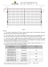
Figure 7
Remark:
1) The length of supporting bars must be longer than the length of module frame, otherwise
please confirm with our product team to get approval.
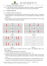
2) As for above figure 6, the solid red rectangles indicate primary clamp installation positions
and the center positions of long frames where clamps can be added for additional support.
3) As for above figure 7, “ ” indicates the allowable installation range of the aluminum clamp,
the recommended installation location is 50~200mm. For this installation, the module's maximum
mechanical test load is 1200Pa for positive and negative.
4) The above figures illustrate the proper installation method of frame surface clamp. “L
±100
”
indicates its mounting location, as specified as follows:
Module type
Dimensions
L±100
L*W*H (mm)
CHSM60M(DG)/F-B
1664*998*30
350
CHSM60M(DGT)/F-B
CHSM72M(DG)/F-B
1980*998*30
450
CHSM72M(DGT)/F-B
CHSM60M(DG)/F-BH
1696*998*30
350
CHSM60M(DGT)/F-BH
1714*1010*30
CHSM72M(DG)/F-BH
2018*998*30
450
CHSM72M(DGT)/F-BH
2038*1010*30