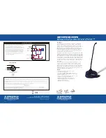
GN15VPD/GN20VPD
Continuously-variable Pattern, Condenser, Mini-gooseneck Microphone with
Integrated Desk Stand, Programmable Switch, LED and Logic Interface
Description
The GNVPD is a series of dual-flex, continuously-variable polar
pattern, miniature-gooseneck condenser microphones with
integrated desk stand, programmable membrane switch, LED,
and logic interface. Special attention has been taken to design the
GNVPD series to resist interference from devices such as cell
phones and two-way communication devices. The integral 80Hz,
12dB/octave high-pass filter removes unwanted low-frequency
energy to improve intelligibility. The cable can easily be made to
exit the bottom or the rear of the stand.
The GNVPD series features logic I/O functions that can be utilized
with automatic mixers, teleconferencing systems and control systems.
The logic input can remotely control the LED as well as membrane
switch activation. The membrane switch working with or bypassing
the microphone’s mute activates the logic output. Bypassing mute
is particularly useful with teleconferencing systems that mute the
microphones after the echo cancellation block. The exact mode of
operation can be set with the DIP switch on the underside of the
desk stand.
The GNVPD has a continuously-variable polar pattern so it can
shorten the list of products an audio system designer needs to
consider when gooseneck condenser mics are specified. The
installer can precisely tailor the polar pattern for the best performance
depending upon the application or environment. The GNVPD is
primarily designed for speech and vocal pickup in governmental,
institutional, and business applications.
Features
• Continuously-variable polar pattern control
• Blue LED status indicator
• Soft-touch programmable membrane switch
• Securable controls on the underside of desk stand
• Keyhole mounting slots
• Logic I/O for external muting and/or remote control
• Available in two lengths (15" and 20")
• RF (radio frequency) Resistant Architecture
• Integrated high-pass filter for elimination of
unwanted low frequencies
• Rear/bottom exit cable design
Astatic Commercial Audio Products
6573 Cochran Rd. Building
I
Solon, Ohio 44139 U.S.A.
Tel: (440) 349-4900 Fax: (440) 248-4902 Sales: (800) 421-3161
www.astaticinstalled.com
©2007 Astatic Commercial Audio Products
Part No. 46873-83-01 June2007
Two-Year Limited Warranty
Astatic Commercial Audio Products hereby warrants that this product will be free of defects in material and workmanship for a period of two years from the date of purchase. In the unlikely
event that a defect occurs Astatic will, at its option, either repair or replace with a new unit of equal or greater value. Retain proof of purchase to validate the purchase date and return it with
any warranty claim.
This warranty excludes exterior finish or appearance, damage from abuse, misuse of the product, use contrary to Astatic’s instructions or unauthorized repair. All implied warranties,
merchantability, or fitness for a particular purpose is hereby disclaimed and Astatic hereby disclaims liability for incidental, special or consequential damages resulting from the use or
unavailability of this product.
This warranty gives you specific legal rights and you may have other rights that vary from state to state. Some states do not allow the exclusion or limitation of incidental or consequential
damages or limitations on how long an implied warranty lasts, so the above exclusions and limitations may not apply to you.
Note: No other warranty, written or oral is authorized by Astatic Commercial Audio Products.
Shipping Instructions
Please call our customer service department at 440-349-4900 for a pre-approved return authorization number.
Carefully repack the unit and return the insured package to: Astatic Commercial Audio Products, 6573 Cochran Road, Building
I
, Solon, Ohio 44139.
RETURNS WITHOUT A
PRE-APPROVED RETURN AUTHORIZATION NUMBER WILL BE REFUSED.
If outside the United States, contact your local dealer or distributor for warranty details.
4 of 4
1 of 4
Logic Interface Details
The logic input, in effect, consists of a 40K ohm pull-up resistor
to the internal microprocessor power supply (1.3V). Pulling
the logic input to ground will activate the logic input.
The logic output, in effect, consists of the open collector of
an NPN transistor. The emitter of this transistor is connected
to ground. When the logic output is activated, current will
flow from the logic output through the transistor to ground.
It is recommended that the pull-up resistance value at the
receiving circuit be kept as high as possible to minimize the
current flow into the logic output. High currents can induce
switching noise into the audio. Absolute maximum current
into the logic output is 50mA.
Connector Wiring


