Associated Research Omnia 8104 Скачать руководство пользователя страница 6

CHANGING

THE

TYPE

OF

TEST

ADDING NEW TESTS

From the Main Menu screen, press the “Setup Tests” soft key.

On the Setup Tests screen, the test and step number will be highlighted.

Press the “Add” soft key and specify the type of test with the soft key options given
(ACW, DCW, IR, Continuity for 8104 and Run Test or Line Leakage Test for 8105
and 8106). 

Once the test has been added, the parameters for the chosen test type will appear.
Use the soft keys to edit parameters on the right side of the screen (examples:
frequency, arc detect, continuity and DUT output).

Use the arrows (up, down, left, right) to scroll between test parameters on the left side 
of the screen (examples: voltage, Hi-Limit T, Lo-Limit T, dwell time, ramp time, etc.).

Use the number keypad to change a parameter value. Once the desired value has 
been entered, press exit to go back to the Setup Tests screen.

If default parameters are acceptable, press exit to go back to the Setup Tests screen.

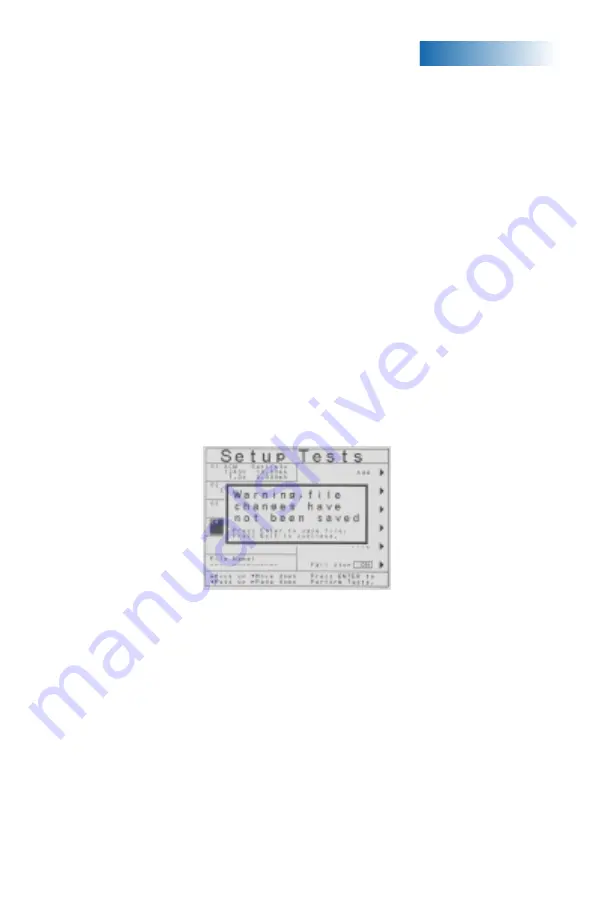
To save the test program, press Exit from the Setup Test screen. You will see the 
following prompt. (See Figure 2)

Press EXIT to continue without saving. Press ENTER to save.

Adding multiple tests to the same screen automatically creates a multiple step test 
sequence. The tests will run in sequential order unless Single Step control is initiated.
To perform single steps, press the PERFORM TEST soft key from the Main Menu
screen. On the right hand side of the Perform Test screen, there is a selection named
Single Step. Press the Single Step soft key to turn Single Step on. The tests will now
run individually. Press Exit to go back to the Main Menu screen.

5

CHANGING TEST SETTINGS AND DELETING TESTS

Test parameters on OMNIA are fully adjustable. Common parameters that can be
adjusted include voltage, Hi-Limit, Lo-Limit, ramp up, dwell time, ramp down, Hi-Limit R
and Lo-Limit R among others.

From the Main Menu screen, press the “Setup Tests” soft key.

(Figure 2. Setup Tests Prompt Screen)


Содержание Omnia 8104

Страница 1: ...est on energized circuitry or equipment BE SURE to always connect the return test lead first HANDLE test clips by insulation only never touch clips directly WARNING THIS GUIDE WAS CREATED FOR OPERATORS HAVING SOME FAMILIARITY WITH HIPOT AND ELECTRICAL SAFETY TESTING A HIPOT TESTER PRODUCES VOLTAGES AND CURRENTS THAT CAN CAUSE HARMFUL OR FATAL ELECTRIC SHOCK TO PREVENT ACCIDENTAL INJURY OR DEATH TH...

Страница 2: ...y used to escape from parameter editing and returning to prior screens 11 UP DOWN LEFT AND RIGHT ARROW KEYS Keys used to scroll the highlighted area or cursor in the specified direction 12 ENTER KEY Key used to finalize parameter entries The ENTER key may also be used to scroll the highlighted area to different parameters in the parameter setting screens 13 SENSE TERMINAL Connector used to attach ...

Страница 3: ... and replacement instructions 6 SCANNER INTERFACE For connection of up to 2 external scanning matrixes 7 CHASSIS GROUND EARTH TERMINAL This terminal should be connected to a good earth ground before operation 8 REMOTE SIGNAL OUTPUT 9 pin D subminiature female connector for monitoring PASS FAIL and PROCESSING output relay signals 9 BUS INTERFACE Standard connector for interconnection of the RS 232 ...

Страница 4: ...rminal input to one side of the measuring device MD and will be enabled during a line leakage test whenever Probe LO has been selected at setup This terminal is provided for performing applied part leakage tests and is always used in conjunction with the Probe HI terminal 8 EXTERNAL MEASURING DEVICE This compartment contains an external measuring device PCB When selected this device will be enable...

Страница 5: ...nel of the instrument OMNIA is equipped with a Remote Interlock feature which utilizes a set of closed contacts to enable the instrument s output In order to perform a test the interlock connector must be plugged into the Signal Input connection of the rear panel of the instrument 4 Turn the POWER switch to ON The initialization screen will appear After three seconds the Main Menu screen will appe...

Страница 6: ...ault parameters are acceptable press exit to go back to the Setup Tests screen To save the test program press Exit from the Setup Test screen You will see the following prompt See Figure 2 Press EXIT to continue without saving Press ENTER to save Adding multiple tests to the same screen automatically creates a multiple step test sequence The tests will run in sequential order unless Single Step co...

Страница 7: ...th the current file now loaded To recall any test file hit the File soft key from the Setup Tests screen Use the up and down arrow keys to select the file to be loaded Hit the Load soft key and the test sequence associated with the file will automatically be loaded Use the arrow keys up down to highlight the test to be edited and hit the Edit soft key Use the soft keys to edit parameters on the ri...

Страница 8: ...his acts as a line and neutral together Plug the Kelvin lead into the Sense jack and the high current test lead into the current jack These two red leads act as the ground connection Connect the ground return clip to dead metal on the chassis of the DUT Plug the Kelvin lead into the Sense jack and the return lead into the return jack Always check to make sure a good connection is made between the ...

Страница 9: ...dapter box into the L terminal and the neutral lead into the N terminal Next attach the red ground lead from the adapter box to the GND terminal Attach the black case return lead into the case terminal Connect the ground return clip to dead metal on the chassis of the DUT Plug the line cord to the DUT into the adapter box receptacle Only the rear output connections may be used for connecting the a...

Страница 10: ...ate a full hand contact to the DUT This foil acts as the return point The Return and Sense jack are attached to the foil Always check to make sure a good connection is made between the DUT and the return clip Attach the high voltage lead to the current carrying conductors of the DUT If performing a ground test on a Class I product connection not shown connect the red high current lead into the Cur...

Страница 11: ...ect the test to be reviewed or use the left and right arrows to page up and page down Results are displayed on the right hand side of the screen including the test type reason for failure and test parameter results Press the EXIT key to go back to the PerformTests screen and hit EXIT again to go back to the Main Menu Figure 7 Results Screen ...

Страница 12: ...ase consult the full Operation and Service Manual or call us toll free 1 800 858 TEST 8378 or 1 847 367 4077 OMNIA 06 08 For more support materials and testing information on OMNIA please visit us online at www asresearch com You can also refer to the Operation and Service Manual ...

Отзывы: