background image

Содержание WORLD'S CAR 6037

Страница 1: ... 6037 1 10 SCALE OFF ROAD KIT INSTRUCTION MANUAL D ONOT DISCARD THIS MANUAL Save for future hassle free re ordering of parts Associated Electrics Inc 3585 Cadillac Ave Costa Mesa CA 92626 ...

Страница 2: ... CHAMPIONSHIP WINNING STEALTH TRANNY NEW REAR BULKHEAD UNIVERSAL DOGBONE REAR AXLES STRONGER PRE MILLED HARD ANODIZED ALUMINUM CHASSIS NEW YELLOW FRONT REAR WHEELS WITH PROLINE TIRES FOAM INSERTS I ...

Страница 3: ...NEW GRAPHITE FRONT REAR SHOCK STRUTS NEW FIBERGLASS BATTERY STRAP NEW BUSHING BELLCRANK STEERING HARD ANODIZED TEFLON SEALED SHOCKS SILICONE SHOCK OIL NEW STRONGER SUSPENSION ARMS CHAMPIONSHIP FEATURES ...

Страница 4: ...r parts bags are referred to by number In the manual While building the car you will sometimes be working with several bags at the same time Inside each major parts bags there are more bags these are not num bered and belong to the bag they came out of 0 Step 2 KEEPTHE PARTS SEPARATE Whilebuild ing the car youwill sometimes be working with several parts bags at the same time Bags and parts will st...

Страница 5: ... is nothing to worry about because we have deliberately left you with some spare items 4 We have used some special abbreviations througholll this manual for the various types of screws used The following list identifies what the abbreviations stand for FHMScrew Flat Head Machine Screw Standard thread screw which requires a Phillips screwdriver FHSScrew Flat Head Socket Screw Standard thread screw ...

Страница 6: ...ide Make sure the balls are mounted on opposite sides of the steering blocks so that they both will be on top of the steering blocks when mounted on the car 4 flat washer rrllmmrn 6273 6936 aluminum 4 40 7260 4 40 thin plain nut 7260 Fig 4 0 Figs 5 6 Remove the two 6220 aluminum lnllne front axles from bag 6 1 fig 6 Install one axle in each 6221 nylon steering blocks fig 7 making sure that the hol...

Страница 7: ...fit of the kingpins remove them again fl t J JI J 6223 Fig 8 0 Figs 9 1O 11 12 Take the two 6210 carrier blocks and install the steering blocks and axles into each one Both ball ends will be on the same side when installed correctly and the raised side of the angle on the bottom of the 6210 carrier block will be away from the ball side Now reinstall one of the 6223 kingpins through each of the car...

Страница 8: ...nterfere with suspension travel 6206 remove Fig 14 a Fig 15Now remove the two 62 26 front inner hinge pins and four 6299 1 8 E clips from bag 6 1 Slip one of the hinge pins into each end of the front suspension arm to chec k the pin fit The A arm should be able to swing freely on the pin Racer s tip Most racers keep a 126 straight reamer in their tool box to free up the suspension arm pin holes an...

Страница 9: ...bag 116 1 you will find two 6262 1 65 long turnbucklesand and in bag 6 14 the 116274 plastic ball end cap molded tree Remove lour or the plastic ball end caps and thread them onto the two turnbuckles The plastic ball endcapson both endswill lace thesame direction Note Each lumbuckle rod has right hand threads on one endand left hand threads on the other so the plastic end caps wf 1 thread on In op...

Страница 10: ...el ball Fig 22 0 Figs 23 24 25 Now we ll al1ach the 6309 nose plate assembly to the new 6302 black hard anodized aluminum chassis You wm see that your chassis fig 23 has already beenmft ed the same as used by ourTeam driv ers In bag 6 2 you will find one 6280 8 32 x 112 alumi num FHMScrew one 6281 8 32 x 7 8 aluminum FHMScrew In bag 6 4 you will find one 6931 8 32 x 114 steel FHMScrew 1 Looking fr...

Страница 11: ...all face the same way on these turnbuck les Adjust the length of the small turnbuckle from cen ter of ball hole to center of ball hole to 1 47 1 15 32 or 37 5mm Then adjust the two longer steering lumbuckles to 2 51 2 1 2 or 63 75mm center to center length di J m n m mu 5 1 11 II_ III_ III_II_IU_ I t 6274 6263 6274 Fig 28 c J 6274 1 47 li lun lml 6 6260 6274 OIIIIIIIIIIOIIIIIHIIIII 60 0 Fig 29 Tak...

Страница 12: ... Now go ahead and install one of the 6263 steering turnbuckles assembled in fig 28 onto the right hand side steel ball ends on the 6221 nylon sleer ing arms and on the M6254 nylon bell crank arms fig 31 Do the left hand side In bag 6 5 remove the 6330 body mount Thread this ontothedriver srightsidescrew as shown in fig 32 Fig 31 Fig 32 0 Figs 33 34 1n bag 6 4you will lind two 6321 blackanodized no...

Страница 13: ...nces are tighter than most other suppliers Due to tight tolerances and careful packaging of matched balls when replacing lost or worn 3132 dlff balls you MUSTreplaceALL 3132 balls altha same I me with new balls from the same package This means you cannot even mix balls from two separate 16581 packages 2 Look at the center hole of the 6580 dill gear if there Is any flash Inside the hole then you wi...

Страница 14: ...iff drive hub it should go in with only a slight amount of pressure to the bottom of the slot Now align the 6575 nylon T nut from the last step with the slots in the 6578 left diff hub and push in theT nut until it contacts the spring steel inset end first WARNING Do not mix up the 16582 diffthrust spring with the 16587 torque control spring in bag E this spring has a slightly larger outside diame...

Страница 15: ...f Lett s Racer s Tip Installing the differential thrust bearing assembly can be a pain but try it this way slideoneofthe thrust washers onto the screwandputsome blackgreaseonthe washer Putallsixthrust ballsin a straight line tn one of the lines on the palm ofyour hand Hold the threadedendofthe screwandroll the greasedwasheralong the row ofballs picking up the balls one at a lime until thsy are stu...

Страница 16: ...he rounded side will be up WARN lNG Ifyou remove the gear at any time before you com pletely assemble the dlff halves always double check to make sure you do not have both drive rings on the same side This can be easy to do because one of the drive rings maystick to the diffgearand the othercouldbe stuck to the diffoutdrive hub on the same side Fig 53 0 Fig 54 low we are going to install the 65781...

Страница 17: ...t and right transmission case halves Make sure that you remove any flashing from the case halves Now go back to bag B and remove four 116906 3 16 x 3 8 unflanged bearings and two 6903 3 8 x 518 sealed unflanged bearings Install the four 6906 bearings in the four small cavities and the two 6903 bearings in the larger cavities inside the case halves as shown 6906 RH 116906 3 8 X 3 16 unflanged beari...

Страница 18: ...all the assembled diff into the right case half lower bearing as shown in fig 60 Make sure that you install the diff bolt head side through the right case half Note If you install the bolt head so that it is on the driver s side of the transmission you may have a problem with the dlff backing off Locate the 6570 idler gear and shaft from bag D and install it into the center bearing of the right ca...

Страница 19: ...that the small ends will go Into the case holes on the right case half as shown in fig 66 Install the 6566 felt seal and spacers overthe drive shaft and onto the case as shown The spacers will also be going over the threaded ends of the four 6935 aluminum case screws Now install the remaining motor plate spacer in the fourth case hole as shown 6569 I Fig 65 Fig 66 0 Figs 67 Now take the 6604 black...

Страница 20: ...h hub with the bushing and clutch disk onto the gear shaft the clutch disk still centered on the hub Make sure that the bushing goes onto the larger portion of the gear shaft and that it Is slightly below the sur lace of the clutch hub when properly Installed 4 From bag E remove the 6594 thrust bushing and two thrust bushing washers You can also remove the 6587 torque control spring and 6629 gold ...

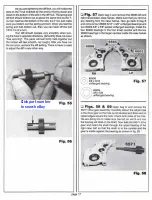
Страница 21: ...he spur gear wHh the two mounting holes in the gear hub and install the screws Your installed spur gear should look like fig 76 when properly secured 6568 4 6693 t Fig 75 11mm 6568 J W 4 40 X 3 16 Fig 76 0 Fig 77 Locate the 6575 dillthrust boltcover weset aside in thefigs 38 39 step On the right dill hub install the dill thrust bolt cover flatside out Push the thrust bolt cover in until it bottoms...

Страница 22: ...sting to race set ting This is done by running the torque clutch adjustment a little on the loose side for about one minute before readjust ing to race settings When you have set the slipper properly you really will not have to alter it much for different tracks If your track is an extremely high traction surface adjust your slipper to prevent wheelies If your track has a low traction surface adju...

Страница 23: ...in fig 84 6932 L JII 4 40 X5 16 1 46932 Fig 83 Fig 84 D Figs 85 86 Nowltlstime tomounttheStealth transmission tothealuminum chassis In bag F ofyourtrans mission bag you will lind four 6292 4 40 x3 8 FHSScrews Place the transmission on top of the chassis as shown in fig 85 making sure the motor plate Is inside the kickup at the end of the chassis Now tum the transmission and chassis upside down and...

Страница 24: ...ill find two 18285 4 40 x 1 4 SHCScrewsand four 6936 4 flat washers This partofthe assembly is very critical Look at the rear chassis and motor plate area as in fig 90 The motor plate rear mounting holes must match the rear chassis mounting holes PERFECTLY Any misalignment here might change the rear anti squat angle If the holes do not match up there are two things you can do You can carefully ben...

Страница 25: ...299 e cllp 1 8 shalt 0 Fig 94 In bag 6 8 you will find four 6280 8 32 x 1 2 aluminum FHMScrews Start by mounting the left hand rear suspension assembly onto the chassis Slide the front edgeofthe 6360 rear mount underneath the rearbulkhead This will line up the two rear mounting holes with the two holes in the chassis Fasten the mount to the chassis using two of the 6280 FHMScrews On the rear screw...

Страница 26: ...rear axle shims Slide two of the shims onto each of the dogbones and then Install the axles into the 6366 rear hub carriers On the outside of the hub carrier install two of the shims and the roll pin Make sure you center the roll pin as best as you can the following photos explain how 6375 6373 0 A 6373 V d spacer I 6371 00 Fig 98 0 Figs 99 100 101 There are twodifferent techniques commonly used t...

Страница 27: ...g with the left hand suspension and turnbuckle snap one end of the turnbuckle onto ball end location A on the rear bulkhead and the other end onto ball end location B on the rear hubcarrier When Installed your turnbuckle should look like fig 104 Now go ahead and re peat the step lor the right side turnbuckle Fig 104 _ SHOCK ASSEMBLY We have made several major Improvements to our new Internal assem...

Страница 28: ...mend having the molded number up so that it will be easier to remember what piston you are using when you service your shocks Fig 109 6299 61Je clip 1 8 shaft 0 Figs 11O 111 1121nanotherplastic bag you will find the new 6440 molded shock assembly parts and 5407 red 0 rings and 6469 black 0 rings Note Part number 116440 is a complete replacement set of 0 rings and plastic assembly parts to rebuild ...

Страница 29: ...utaway drawing but depictsthe shock assemblytool removing the shockseal parts In order to dismantle the shock seal parts you must 1 remove the shock cap 2 drain the shock oil 3 and removetheshockshaftwithpiston 4 Insertthesmall angled tip of the shock tool into the bottom of the shock 5 First slide the tool all the way in until the tool bottoms out against the shock body 6 Now angle the tool sligh...

Страница 30: ...nto the shock cavity 2 Now stand the shock tool on your workbench with the shock body on top and firmly push down on the shock body until you hear and feel the split washer snap Into its groove You may have to push hard before it will go ln 3 When properly installed the end of the shock tool should be sticking out the bottom of the shock about 1 8 4 Once the pans have been prop erty snapped into p...

Страница 31: ...y to the top 2 Now move the shock shaft up and down slowly several times to make sure that there are no air bubbles trapped under the piston 3 If there were air bubbles refill the shock until it is within 1 16 of the top 4 Now push the shock shaft up until the piston is ct051 to th top of the shock body but still completely covered by the otl 5 Now thread your 86439 black aluminum shock cap they a...

Страница 32: ...nd onto the shock shaft To keep the shock shaft from turning you will have to hold the shaft with your needle nose pliers WARNING Using only the smooth part of your needlenose pliers grab only the shaft not the threads and as close to the threads as possible This is vel llmportant for we do not want to scratch the shaft where it will ride in the 0 rings for this could damage them causing the shock...

Страница 33: ... screws the flange of the bushing toward the nut Fig 132 0 Figs 133 134 135 1 Go back to bag 6 1 and take out the two 6930 4 40 x 3 4 Special SHCScrewsthat have threads only on the end 2 Take one ofthe front shocks and slide the shock pivot ball end into the front suspension arm mounting slot as shown in lig 133 Into the outside hole ol two mounting holes This photo shows installing the passenger ...

Страница 34: ...ar shock screwing it into the outside mounting hole on the rear A arm as shown In lig 136 3 Make sure that the screw goes through the small end of the pivot ball and that the flat side will mount against the rearA arm as shown 5 Now install the upper end of the right rear shock overthe 6473 nylon shock bushing 6 Thread on the 6222 4 40 5 40 black nylon self threading nut from bag 6 9 Tighten the n...

Страница 35: ...and some will be quite difficult to Install For these tough ones soapy water Ike dish washing soap will help the rubber to slip easier and will make mounting the tires much simpler Be sure to rinse off the soap and dry the tires thoroughly 6860 QUHJI 111 4 40 X 3 8 aluminum 6906 318 X 3116 unflanged bearing Fig 139 0 Fig 140 This photo shows the 6854Y front wheel ring already installed Double chec...

Страница 36: ...tains two Associ ated 6824 Proline XTR 118086 flat stubby rear tires two 16805YYellow2 175 one pieoe rearwheels and two 6860 light grey or blue foam tire Inserts Remove the 6824 tires and the 116880 foam Inserts Pull the center out of the foam inserts and discard it Push the foam inserts into the rear tires and center the foam In each tire Your tire with foam inserts should look like fig 146 Now t...

Страница 37: ...0 151 In bag 6 7 you will find the 6334 nylon battery cup and two 116922 4 40 x 112 FHSscrews Use the two 6922 FHSScrews to fasten the battery cup to the chassis as In fig 150 Now get the two 116924 4 40 x318 SHCScrews and the 6339 fiberglass battery hold down strap from the bag Thread the two 6924 SHCScrews into the two holes on top of the battery cup as shown in fig 150 To install the battery st...

Страница 38: ...or 4735 from J R Propo There are many more servos available than what are listed here but these represent what seem to used by most racers If you are running one of the new all metal gear servos or if you feel your driving is good enough you may choose to run a standard servo horn and no servo saver If you makea mistake and hit something hard enough though then you can damage your servo s internal...

Страница 39: ...4 40 small pattern nut Thread on the ball end in the hole closest to 3 4 75 or 19 1mm on the correct sideaccording toyourmeasurements Not Onmost seNo horns or seNo savers you will have to enlarge the mounting hole before you instal the bell end The best way to do this is to ream out the hole with your X actoO knife Reaming from both sides willhelpprevent the seNOhom or saverfrom cracking After the...

Страница 40: ...wo of the 6936 4 aluminum flat washers under each mountto raise them Now remove the twoservo mounts and drill your marked holes with a 43 drill bit a 3 32 drill bit will worl if used carefully Fig 159 0 Fig 160 Now remove two 6936 4 aluminum flat washers and two 6919 4 40 x 5 16 BHSScrews from bag 6 6 Use these screws and washers to mount the servo to the servo mounts as shown Reinstall the servo ...

Страница 41: ...you have a high frequency speed control without reverse like the Novak HPc orTekin 411 G you should Install a Schottky diode This diode will give you moreconslstenlbrakes make your motor run more efficiently and allow your electronic speed control to run cooler The diode has a silver band painted on one end that is used to identify the positive side of the diode Connect the diode to the tabs of th...

Страница 42: ...d the upper and lower motor screws and washers into the motor but do not completely tighten the screws yet 6 Now we need to set the gear mesh By moving the motor forward or back we will be moving the motor pin ion gear closer to or away from the nylon spur gear What we want to do is the get metal pinion gear as close to the nylon spur gear as we can without jamming the gears The easiest way to che...

Страница 43: ...rvo and an electronic speed control make sure it is a good ESC Most racers prefer to use aftermarket speed controls from companies like Novak or Tekin which are the two top manufacturers of ESC s 0 Fig 172 173 174 1 Locate your re ceiver close to the antenna on the right side of the chassis as shown Ifyour receiver is too large to fit laying down you will have to stand it on edge If you have to do...

Страница 44: ...nted we can install the steering servo plug into the channel 1 or rudder slot on the receiver Bundle the excess steering servo wire and secure it with one of the small wire tires supplied with the kit Try to keep the excess wire as far away from the receiver as possible Fig 175 0 Fig 176 177Mount yourspeed control as far back on the driver s side of the chassis as possible using another piece of s...

Страница 45: ...r batteries is to keep the positive leadas short aspossible This helps reduce power loss and improves ef ficiency Therefore because the speed control ESC is in the driver s side corner the positive terminal of our battery pack should be in the same corner Also for ourbattery pack to have the right voltage for our application the cells will need to be soldered in series This means the positive end ...

Страница 46: ...tor is in the bac k left comer 2 Now push the pins into the pin sock ets We are doing this so we can measure the wire lengths before we cut them Make sure you leave a little slack in the wires so lhat they will not be hard to push in or pull out of the sockets 3 Now solder the negative wire to the nega live pin connector and the positive wire to the positive pin connector 4 Because the speed contr...

Страница 47: ...189 Go ahead and install your battery hold down strap over your batteries If you do not remember how you can refer back to figs 149 to 151 Your completed car will now look like figs 186 189 Fig 186 Fig 187 Fig 188 page 47 ...

Страница 48: ... mask off is the section which will be Fig 189 painted white The next coloryou maskofisthe lightest c lor next towhite and soon Keep this in mind when you des1gn MASK your body and wing the more time spent in masking the betterthe finalresults Useautomotive masking tapeforthebestresults Pressall edges ofthe tapedownwith a Popsicle stick or your fingernail Put some masking tape on the outside of th...

Страница 49: ... only product that we have found that can remove the paint or overspraywithout damaging the Lexan isSynthetic Reducer If used property It can be purchased through a automotive paint supply store Fig 190 Fig 191 Fig 192 page 49 Fig 193 Fig 194 ...

Страница 50: ...After the body is finished place non the chassis so that both body mounts are coming through the body holes Now install the 6332 body clipsthrough the body mounts Fig 195 shows the front of the body with the bodyclip Installed fig 196 shows the wing mounted Fig 198 shows the finished product Fig 195 Fig 196 Fig 197 page 50 ...

Страница 51: ...ruction manual It is also a handy supplement to the Team Associated 1 10 scale off road buggy catalog You can use the manual photos and descriptions to identify part numbers and names to help you order parts Use the current catalog for pricing page 51 ...

Страница 52: ...0 St ilTEAM ASSO l t 1994 Associated Electrlcs Inc 3585 Cadillac Ave Costa Mesa CA 92626 714 850 9342 ...

Отзывы: