Assa Abloy Securitron UNLATCH UNL-12 Скачать руководство пользователя страница 3


PN# 500-18300


Page 3 

Rev. D, 08/11 

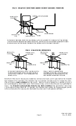
FIG. 3:  MOUNTING ON WOOD DOOR WITH ANSI 2 3/4” STRIKE 

ANSI 2 3/4"

STRIKE

STOP

DRAW VERTICAL LINE

THROUGH EDGE OF

STRIKE HOLE WHICH

CAPTURES LATCH

DRAW HORIZONTAL

LINE BISECTING

STRIKE HOLE

USE THIS LINE TO

CENTER THE

UNLATCH

VERTICALLY

SET THE HORIZONTAL

POSITION OF THE UNLATCH

SO THAT THE SEPARATION
OF THE TWO PLUNGERS IS

1/16" FARTHER FROM THE

STOP THAN THE VERTICAL

LINE YOU HAVE DRAWN

1/16"

TEMPLATE IS MARKED TO

SET VERTICAL AND

HORIZONTAL ALIGNMENT


First, draw two lines with a pencil on the door frame (see Figure 3). 

 
The first line is horizontal and bisects the 2 3/4” ANSI strike.  The second is vertical and 
extends the edge of the strike opening
 which captures the latch.  Next, remove the strike 

and introduce the template.  Note that the template shows a center line arrow which you 
will use to position the UnLatch vertically by lining it up with the center line you have previously 
drawn.  Next, the template has arrows at the top and bottom which line up with the vertical 
extension line you have drawn.  These arrows position the UnLatch horizontally so that the 
separation between the two UnLatch plungers is 1/16” farther from the stop than the edge of the 

ANSI 2 3/4” strike.  The latch is captured by the UnLatch at the separation line between the 
plungers and moving this position somewhat away from the stop increases adjustability of the 
installation. 
 
When you have the template correctly positioned, mark your top and bottom mounting holes.  
Then you will need to chisel out a shallow space 3/32” (2MM) under the complete outline of the 

UnLatch and chisel a rectangular cut-out as the template shows, 1 3/4” (44.5MM) deep to admit 
the UnLatch body.  As you get close to finishing the chiseling job, experimentally try to fit the 
UnLatch body in the cavity.  This will avoid chiseling too big a space.  A tight fit is preferred as 
it helps the solidity of the mounting which is important if the door receives abuse.  Normally, 
with a wood frame, the wires will be run inside the wall.  Simply drill from the back of the cavity 

you have created rearward into the wall space to admit the wires into the walls.  To mount the 
UnLatch to the wood frame, use the two furnished #12 x 1” flat head wood screws. 
 
Note finally that we have implied that there are only two types of strikes on wooden doors: the 
ANSI 4 7/8” and the ANSI 2 3/4”.  In residential applications there are also square shaped 

strikes (particularly found with inexpensive imported latches) which are smaller in outer 
dimensions than the 2 3/4” strike.  These pose no difficulties.  The installation techniques are 
the same as for an ANSI 2 3/4” strike. 
 
2.4  FINAL ADJUSTMENT WITH SPACERS 
For reliable operation, the door needs to close so that the latch easily enters and is retained by 

the UnLatch.  The door should not have to be pushed to engage as can be the case with a poorly 
fitting or poorly closing door.  To check this point, when the UnLatch has been mounted, after 
the door is closed and latched, you should be able to “rattle” the latch against the UnLatch 
plunger by pushing the door in and out.  The amount of movement in the door latch should 
be about 1/16-1/8” (1.5-3MM).


If the amount of slack or rattling is greater than 1/16-1/8”, you need the door to “close 
earlier”.
  In effect, the edge of the stop needs to be closer to the UnLatch.  To adjust for this, 
first check to see if the stop has “silencers” on it.  These are cylindrical rubber bumpers which 
quiet the noise of a closing door but also have the effect of making the door close earlier.  If you 

have silencers and the door is still rattling too much, contact the factory for additional door stop 
spacers (the UnLatch is shipped with two).  If you don’t have silencers, add one or two door stop 
spacers as is shown in Figure 4 to cause the door to close earlier. 
 

Содержание Securitron UNLATCH UNL-12

Страница 1: ... operating 3 Amp input surge 12 VDC 1 5 Amp input surge 24 VDC for 100 milliseconds and 300 mA 12 VDC or 200 mA 24 VDC thereafter Operating Temperature 10 F to 125 F FIG 1 UNLATCH DIMENSIONS INCHES 4 87 1 245 3 37 4 12 3 38 1 50 1 33 RECOMMENDED TOOLS MEDIUM PHILLIPS DRIVER MEDIUM SLOTTED DRIVER CHISEL WIRE CUTTER STRIPPER VOLT OHM METER CRIMP CONNECTORS CRIMP PLIERS 2 PHYSICAL INSTALLATION 2 1 SU...

Страница 2: ...OOD FRAME MOUNTING Installation in a wood frame is straightforward It is a question of using a chisel to create a space for the UnLatch behind the existing strike The procedure depends on whether you have a 4 7 8 ANSI strike commercial or a 2 3 4 ANSI strike residential on the door In the case of a 4 7 8 ANSI strike you will be using the existing holes that mount the strike to mount the UnLatch Re...

Страница 3: ...is will avoid chiseling too big a space A tight fit is preferred as it helps the solidity of the mounting which is important if the door receives abuse Normally with a wood frame the wires will be run inside the wall Simply drill from the back of the cavity you have created rearward into the wall space to admit the wires into the walls To mount the UnLatch to the wood frame use the two furnished 1...

Страница 4: ...it card in between the door and frame To forestall this the deadlatch was created The deadlatch includes a deadlatch pin which is depressed against the flat part of the strike when the door is closed When the deadlatch pin is depressed the latch cannot be pushed in by a credit card for instance it is mechanically blocked Deadlatches therefore offer a considerably higher level of security and this ...

Страница 5: ... WHICH ALLOWS THE DEAD LATCH PIN TO COME OUT THIS UNFREEZES THE SPRING LATCH FINALLY BOTH PLUNGERS MOVE FORWARD TOGETHER THIS PUSHES OUT THE SPRINGLATCH AND DEADLATCH PIN AND THEREBY RELEASES THE DOOR Note that if the door is heavily pre loaded by someone trying to pull it open before the UnLatch has released it for example the UnLatch may not possess enough power to release the door This is terme...

Страница 6: ...onal electric strikes the UnLatch is fail secure which means that it will maintain the door in a secure position if power is lost Entry is not possible but people can of course exit by simply turning the door handle or knob from the inside FIG 7 UNLATCH WIRING WHITE STATUS COM BLUE STATUS N O CLOSURE BETWEEN V IN AND TRIGGER RELEASES LATCH ORANGE TRIGGER GREEN STATUS N C POWER SUPPLY RED V BLACK N...

Страница 7: ...re being operated from the same power supply If therefore your installation includes a digital keypad or other microprocessor equipped device make sure you have full power supply capacity or use a separate power supply for the keypad or other device 4 2 WIRE GAUGE SIZING If the power supply is some distance from the lock voltage will be lost dropped in the connecting wires so that the UnLatch will...

Страница 8: ... dead latch pin would be resting on the metal strike casing of the UnLatch In this condition if the UnLatch was allowed to operate the dead latch plunger would attempt to push the spring latch and it would be unable to do so because the dead latch pin would be pushed in by the metal casing of the UnLatch The motor would jam The UnLatch senses any motor jam condition and shuts itself down for that ...

Страница 9: ... and this can crash the microprocessor A crash can also occur as a random event but this is unusual There are two recovery methods that may be used to recover the unit s operation The first technique is a simple reset achieved by cycling power to the unit Remove power V from the unit s red wire momentarily After power is reapplied the unit may reset and begin normal operation If this recovery meth...

Страница 10: ...EMPLATE FOR CUTTING OUT ANSI 2 STRIKE PREPARATION AND INSTALLING UNLATCH ON WOODEN FRAME DOTTED LINE SHOWS AREA TO CHISEL OUT 1 3 4 DEEP FOR INSTALLATION IN WOOD FRAME 4 7 8 1 1 4 4 1 8 CENTER LINE HORIZONTAL ALIGNMENT ARROWS SEE FIG 3 ...

Отзывы: