1
500-22090, Rev A
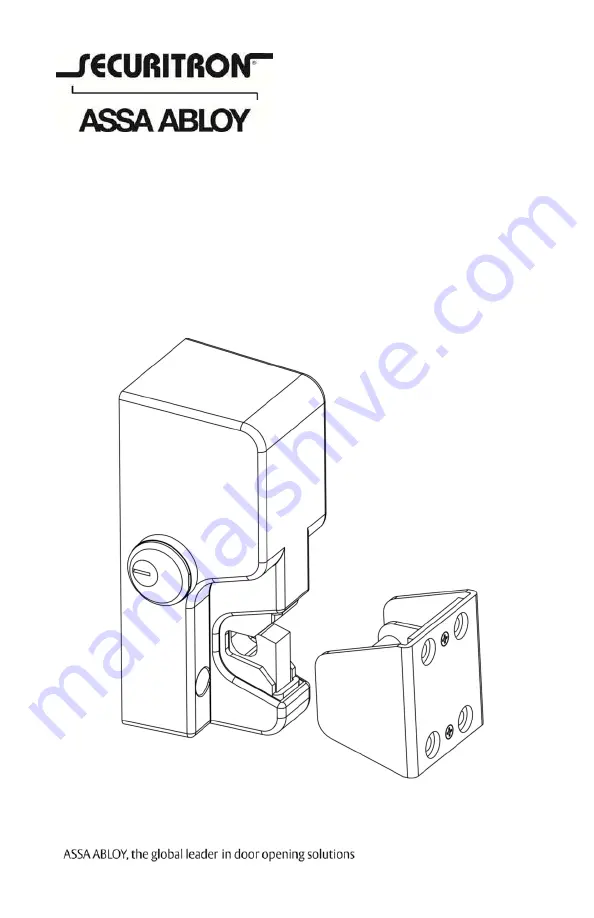
GL-1 Gate Lock
Installation Instructions and Operating Manual
Страница 1: ...1 500 22090 Rev A GL 1 Gate Lock Installation Instructions and Operating Manual...
Страница 2: ...t Components 4 Recommended Tools 4 Installing the GL1 Electromechanical Gate Lock 5 Perform a Pre Installation Survey 5 Perform the Cylinder Lock Cover Hole Plug Installation 8 Mount the GL1 and Conne...
Страница 3: ...emperature 58 to 167 F 50 to 75 C Product Overview The GL1 Electromechanical Gate Lock is designed to secure a wide variety of vehicle and pedestrian gate applications where security and weather resis...
Страница 4: ...rface Mount Black finish Product Components Upon unpacking this product an inventory should be made to ensure that all the required components and hardware have been included Along with these instruct...
Страница 5: ...ion with the conduit opening on the bottom The GL1 should not be used for dual swing gates Perform a Pre Installation Survey Due to the variety of mounting configurations available with this product i...
Страница 6: ...elding adequate size metal plates channels or tubing to the fence frame and the gate Formed angle and brackets along with appropriately sized fasteners may also be utilized to mechanically secure moun...
Страница 7: ...7 500 22090 Rev A Figure 3 Installation Spacing Dimensions Figure 4 Chassis Welding...
Страница 8: ...t convenient for the key access after installation if installing the optional manual override 2 INSTALL the optional cylinder lock NOTE The following step is critical to the proper operation of the me...
Страница 9: ...t in place using the provided cylinder nut tool f INSTALL a cover hole plug in the opposite side of the cover and SECURE its retaining nut using the provided retaining nut tool NOTE The following step...
Страница 10: ...f the recommended mounting bracket kits THEN USE the included template to locate and install mounting hardware 2 INSTALL the lock chassis using the top two lock chassis mounting positions NOTE The fol...
Страница 11: ...chassis see Figure 7 Wire Routing 4 FEED wires through the hole in the side of the lock chassis opposite to the cylinder lock if installed 5 IF there is no cylinder lock installed THEN FEED wires thro...
Страница 12: ...12 500 22090 Rev A Figure 8 PC Board Terminal Block Figure 9 System Connections 7 PERFORM a functional test of the GL1...
Страница 13: ...GL1 FL Applying input voltage of 12 or 24 volts DC observing polarity See Wiring diagram below will energize and unlock the Gate Lock allowing the gate to be opened Removing the input voltage will de...
Страница 14: ...d strike are physically latched CHECK for damage to monitor lever PROBLEM The lock does not release CHECK for excessive pre load to lock the gate lock latching mechanism is not designed to release und...
Страница 15: ...nstalled and functions properly REVIEW installation instructions and CHECK rotation direction Check wire routing to ensure that the placement of the wires does not impede the rotation of the cam or mo...
Страница 16: ...0 Rev A Securitron 10027 S 51st St Ste 102 Phoenix AZ 85044 Tel 1 800 624 5625 Mon Fri 6 00am 4 00pm PDT Fax 1 800 232 7329 s e c u r i t r o n c o m 2014 Hanchett Entry Systems I nc an ASSA ABLOY Gro...