background image


PN# 500-16900


Page 10 

Rev. D, 12/11 

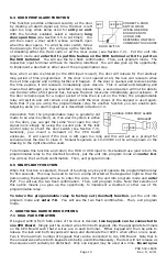
As mentioned at the beginning of this section, here is the procedure to follow if you don’t get a 
steady yellow light on power up
.  The absence of the yellow light means that for any reason, 
the unit already has one or more codes in memory.  You must erase these other codes to be 

certain that the unit will operate only on the codes you plan to enter.  Follow the steps shown 
below. 
 

Press the “Hard Code” button on the CPU board for one second. 


Confirm slow flashing yellow LED  


Press the Bell key (yellow flashing stops).  Confirm two red flashes 


Press the “Prgm Code” button on the CPU board for one second. 


Confirm fast flashing yellow LED  


Enter 8-8 followed by the Bell key (or wait 5 seconds).  Confirm two red flashes 


Extinguish the fast yellow flashing LED by pressing the Bell Key or waiting 30 seconds 

This procedure has erased any Hard code that was present (see Section 4.1) and all user codes.  
The yellow LED will usually come on steadily.  If it doesn’t, it means that the unit has a previous 

Program code in memory and this is no problem as you will be overwriting the old Program code.  
Return to the beginning of this section for keypad changeable programming. 
 
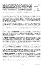
4.2.1  CHANGING THE USER AND PROGRAM CODE FROM THE KEYPAD 
This is the day to day procedure that should be taught to the end user.  Normally the end user 

will not access the CPU board.  Everything should be done from the keypad.  To change the User 
code: 
 

Enter program code, followed by the Bell Key, note rapid yellow flashing LED (program 

 mode) 
 

Enter prefix 0-1 followed immediately by a new 2-7 digit User code 


Wait 5 seconds 


Note two red LED flashes for confirmation, note rapid yellow flashing LED returns 


Press Bell key to terminate program mode or wait 30 seconds 


Re-enter new User code (door should open) 

The program code should need changing much less often.  To do it: 
 

Enter old program code followed by the Bell Key, note rapid yellow flashing LED 

 (program 

mode) 


Enter prefix 0-0 followed immediately by a 5-7 digit new Program code 


Wait 5 seconds 


Note two red LED flashes for confirmation, note rapid yellow flashing LED returns 


Press Bell key to terminate program mode or wait 30 seconds 


Re-enter new Program code followed by the Bell Key (to test it), note rapid yellow 


flashing LED returns 


Press Bell key to terminate program mode or wait 30 seconds 

The logic behind this procedure is as follows.  All programming for the DK-26 starts with putting 
the unit into program mode (except entering the single Hard code).  The unit is put into program 

mode by either pressing the “Prgm Code” button on the CPU board or entering a valid program 
code.  When you enter a program code, however, you have to terminate the sequence with 
the Bell Key
.  This is for a little extra security.  An unauthorized person who came across a 
copy of the Program code might not know he had to press the Bell key after entering it.  The 
prefix 0-0 causes the code which follows to be stored as the Program code.  The prefix 0-1 

causes the code to be stored as a user code. 
 
4.2.2  ADDING MULTIPLE USER CODES 
The DK-26 has memory locations for up to 59 User codes.  This allows separate codes for 
individuals or groups which is a benefit because when one code is changed (usually owing to a 
security worry), the people who use the other codes don’t have to learn a new code.  To 

Содержание Securitron DK-26

Страница 1: ...500 16900 Rev D 12 11 ASSA ABLOY the global leader in door opening solutions MODEL DK 26 DIGITAL KEYPAD SYSTEM INSTALLATION AND OPERATING INSTRUCTIONS Securitron Magnalock Corp www securitron com Tel...

Страница 2: ...PROGRAMMING Page 8 SECTION 4 2 KEYPAD CHANGEABLE PROGRAMMING Page 9 SECTION 4 2 1 CHANGING THE USER AND PROG CODE FROM KEYPAD Page 10 SECTION 4 2 2 ADDING MULTIPLE USER CODES Page 10 SECTION 4 3 MAST...

Страница 3: ...eypad is pulled down firmly on to the screw A 3 8 10MM hole is then drilled for the cable After the cable has been pulled through the final screw secures the keypad to the wall Note finally that a bla...

Страница 4: ...which could cause the microprocessor to malfunction The MOV should be spliced into the lock power wires as close to the lock as possible Some DC electric locks have internal kickback protection includ...

Страница 5: ...om an AC transformer when the DK 26 is used Select a transformer of the same voltage as the lock 12 or 24 The CPU board converts the input AC to DC to operate the lock Make sure the capacity of the tr...

Страница 6: ...DK 26 and the lock The DK 26 does not require regulated power but certain specialized electric locks do so follow the rule of matching the power supply to the requirements of the lock DC locks come i...

Страница 7: ...to send power to the lock Figure 6 shows how to add external contacts for non timed remote release of the lock for both lock types FIG 6 ADDING EXTERNAL CONTACTS FOR FAIL SAFE AND FAIL SECURE LOCKS NC...

Страница 8: ...while its normally open contacts activate the DK 26 In effect the lock is released twice Note that the NC contacts are placed in the circuit before the DK 26 s lock control relay This is to aid possi...

Страница 9: ...programming in a situation where the end user is not likely to ever change the code or at least that changes would be rare Fixed programming can be used in lower security traffic control applications...

Страница 10: ...ixed code programming 4 2 KEYPAD CHANGEABLE PROGRAMMING In this application two codes are programmed into the DK 26 The first called the Program code acts as a password which allows changing the User...

Страница 11: ...ately by a new 2 7 digit User code Wait 5 seconds Note two red LED flashes for confirmation note rapid yellow flashing LED returns Press Bell key to terminate program mode or wait 30 seconds Re enter...

Страница 12: ...code The unit could not be put into program mode from the keypad The DK 26 however avoids this problem by rejecting any code that is a subset of another code in memory It signals this rejection by sh...

Страница 13: ...y by entering a User code and then secured all night by entering a User code again When you have enabled toggle mode activation of the REX input will successively energize and deenergize the lock cont...

Страница 14: ...inary operation must be via one or more User codes see Section 4 2 for programming Program the Hard code as your duress code see Section 4 1 Put the unit in program mode and enter 7 5 You will see the...

Страница 15: ...e simply by using the second pole of the lock control relay to shunt the door switch see Section 7 3 Generally you mount a Sonalert on the CPU board enclosure It will sound if the door is left open to...

Страница 16: ...e terminals 7 3 ALARM SYSTEM SHUNTING The DK 26 s lock control relay is of the double pole double throw type Note that in all the other drawings in this manual we show only one of the poles being used...

Страница 17: ...K 26 is often used with Securitron s Touch Sense Bar and magnetic lock The following drawing shows wiring for this particular configuration Note that the REX input is not used Since touching the bar o...

Страница 18: ...timer Two digit codes must be entered from 01 to 99 seconds Default is 5 seconds Entering 00 sets toggle mode APPENDIX B TROUBLESHOOTING Note first that the DK 26 replaces older Securitron keypads the...

Страница 19: ...nt through the PolySwitch trips it so that it clamps the current down to roughly 100 mA The PolySwitch will continue to clamp until all power is removed for about 5 seconds It is not enough to correct...

Страница 20: ...ace the keypad for full operation PROBLEM Unit beeps when keys are pressed but does not accept programming If the problem occurs on initial installation usually it s caused by misunderstanding the pro...

Страница 21: ...ry slot 45 You test the code by re entering 4 5 1 2 and the door opens because the sequence includes the real code 1 2 Later it will be noticed that the door is opening on 1 2 as this is such a simple...

Страница 22: ...a fail secure lock is operated from the same supply as the DK 26 When the lock is energized it may draw too much power for the power source This reduces the voltage and these voltage swings can crash...

Страница 23: ......

Отзывы: