background image

11

BHL Trim

Installation Instructions

8200 Series

A8131F  08/19

Copyright © 2019, SARGENT Manufacturing Company. All rights reserved. Reproduction in whole or 

in part without the express written permission of SARGENT Manufacturing Company is prohibited.

1-800-727-5477 • www.sargentlock.com

Outside Lever Rehanding (Optional)

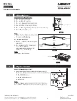
 Assemble Outside Adapter Plate and Rose

•  Insert two (2) mounting posts into  

adapter plate. (Figure 27)

•  Install rose using four (4) security  

Torx screws.

Note 

Tighten screws evenly.

Install Outside Lever Assembly

•  Insert spindle into bushing; ensure that spindle is inserted no more than ¾" deep. 
•  Use spindle to rotate bushing clockwise into outside lever hole.
•  Fully tighten bushing, then unthread bushing just enough to allow spindle to be inserted into lever, 

keeping bushing as tight as possible.

•  Once assembled, spindle orientation should be as shown. (Figure 28)

Note 

Longer spindle used on outside. 

Figure 28 

Note position and orientation of spindles.

LH Outside

RH Outside

LHR Outside Shown

Make sure spindle seats into clutch 

adapter, then proceed to step 4d to 

retain Outside Trim on door.

(4) Security Torx Screws

Rose Assembly

Adapter and Plate Assembly 

with Mounting Posts

LH/LHR Outside Shown

RH/RHR Outside Shown

Figure 27 

Содержание Sargent 8200 Series

Страница 1: ...he express written permission of SARGENT Manufacturing Company is prohibited 1 800 727 5477 www sargentlock com WARNING This product can expose you to lead which is known to the state of California to cause cancer and birth defects or other reproductive harm For more information go to www P65warnings ca gov BHL Trim For Mortise Locks 8200 Series ...

Страница 2: ...ng Is Tight 9 c Install Outside Trim 9 d Install Inside Rose Adapter Plate 10 e Install Inside BHL Rose Assembly 10 f Install Inside Lever Assembly 10 9 Outside Lever Rehanding Optional 11 a Assemble Outside Adapter Plate and Rose 11 b Install Outside Lever Assembly 11 Attention Installer Please read these instructions carefully to prevent missing important steps Notes Improper installation may re...

Страница 3: ...r 82 5621 Rose Packet 82 5618 BHL Screw Packet 1 3 4 Door Inside Outside 82 5597 InsideLeverAssembly Figure 1 h 3 Lock Handing NOTE Red surface of locking piece must face Secure side of door To rotate locking piece 1 Position lockbody with red surface of locking piece visible 2 Insert blade type screwdriver into locking piece slot to rotate locking piece 3 Push locking piece toward back of lockbod...

Страница 4: ...self adjusting To change hand of latch 1 insert screwdriver blade into the spade shaped slot 2 Rotate screwdriver 90 to push latch out until back of latch clears lock front Rotate latch 180 Latch will re enter lockbody NOTE Latch cannot be unscrewed 4 Change Lock Function How to change function of lock Green catch screw must be located in following three 3 locations as designated on lock case to c...

Страница 5: ... Store Room Closet Lock X X X 05 F04 Office or Entry Lock X X X X 06 Store room or Service Lock X X X 13 D31 Communicating or Exit Lock X X 31 Utility Lock X X X 36 Closet Lock X X X 37 F05 Classroom Lock X X X 38 F32 Classroom Security Intruder Latchbolt Lock X X X X 41 Cylinder is standard for both single double cylinder functions for 1 3 4 thick door 130 KB thumb turn is used with rose trim onl...

Страница 6: ...screw into each rose Use a 5 64 hex key to tighten screw firmly to rose Figure 8 Figure 8 LH LHR Outside or RH RHR Inside Security Rose BHL 01 9641 Button Head Screw 6 32 X 7 16 LG RH RHR Outside or LH LHR Inside 6 Door Preparation Important Be sure to hand the lockbody before installing 1 Insert mortise lock into door and fully tighten 1 lock mounting with two 2 wood screws and two 2 machine scre...

Страница 7: ...ce marker spindle into lockbody on outside of door NOTE Use blade side of door marker spindle Figure 10 6 Coin turn functions only Slide turn piece door marker template over spindle 7 Coin turn functions only Mark two holes for coin turn Figure 12 8 Remove lockbody from door 9 Turn piece functions only Drill one middle hole 290 And two outer holes 3 8 halfway through door Figure 13 10 Coin turn fu...

Страница 8: ...ake sure lock is unlocked Figure 16 7 BHL Trim Installation 1 Install strike using 3 4 strike mounting screws NOTE Strike must be oriented with strike lip towards pull side of door Figure 10 2 Cylinder functions only Slide cylinder s through spring spacer and collar threading into lockbody until cylinder face is flush with collar Figure 11 Figure 17 Figure 18 Strike Lip NOTE Pull key slightly out ...

Страница 9: ... ensure that spindle is inserted no more than deep Use spindle to rotate bushing clockwise into outside lever hole Fully tighten bushing then unthread bushing just enough to allow spindle to be inserted into lever keeping bushing as tight as possible Once assembled spindle orientation should be as shown Figure 23 Figure 22 Bushing Outside Rose Adapter Plate Assembly Align rose screw with gap in sp...

Страница 10: ...using four 4 security Torx screws Tighten screws evenly Figure 25 Figure 25 IMPORTANT Screw oriented towards latch Security Torx Screws LHR Inside Shown f Install Inside Lever Assembly Install inside spindle Figure 26 Install inside BHL lever assembly to inside adapter plate assembly using security Torx set screw IMPORTANT Line up rose screw with gap on spring cartridge Make sure machined end of s...

Страница 11: ... Assembly Insert spindle into bushing ensure that spindle is inserted no more than deep Use spindle to rotate bushing clockwise into outside lever hole Fully tighten bushing then unthread bushing just enough to allow spindle to be inserted into lever keeping bushing as tight as possible Once assembled spindle orientation should be as shown Figure 28 Note Longer spindle used on outside Figure 28 No...

Страница 12: ...plications The company s customer base includes commercial construction institutional and industrial markets Copyright 2019 SARGENT Manufacturing Company All rights reserved Reproduction in whole or in part without the express written permission of SARGENT Manufacturing Company is prohibited SARGENT Manufacturing Company 100 Sargent Drive New Haven CT 06511 USA 800 727 5477 www sargentlock com A81...

Отзывы: