background image

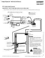
Sample Wiring #2 – 57-  Exit Device with inside Keypad, Fire Alarm, Door Status and Remote Horn  

A valid code entry at the 4291 (Inside) keypad shunts the 57- exit device and allows egress for a time period programmable at 

the keypad. During a fire alarm condition, the contact opens which de-energizes the external electromagnet and allows immedi-

ate egress. When the rail is armed and the door is forced open, the 3287 door status switch signals the rail sounding the rail 

alarm. 

System Wiring Examples (Continued) 

9

3520 24VDC 1.0AMP Regulated and Filtered Power Supply  

5, Orange (EI)  

Red

 (+24), 

2  

6, Blue (DS)  

Normally Closed Fire  

Alarm Contact 

(If Required)  

7, Brown (Mag

 -

)  

Black (-24), 1


Green (EG), 4  

2  

4  

7  

6  

3  

1  

5  

Pigtail harness 

assembly with 

8-pin connector  

Red (+)  

Black (-)  

1584  

Electromagnetic  

Green(NC) 


Lock  

White (C)  

3287  

Door Status  

Switch  

(

-

)  

Plug pigtail harness 

connector into  

C  

8-pin hinge connector 

at frame side  

NO  

1  

 2   3  

4291 

Keypad  

of door  

4  

 5   6  

7   8   9  

(Inside)  

57- 80 Series Rail 

with 8-pin connector  

0   #  

(+)  

*  

Electric Hinge with 

8-pin hinge connector  

Raceway harness with  

8 & 4-pin connectors.  

The 4-pin connectors are not  

used here.  

Line voltage 

fuse (1 AMP) 


Connector to     

power on LED

HOT  

110-120 VAC  

NEUT  

GND  

AC 

F  

Low voltage AC 

From transformer  

AC  

DC  DC  

Output  

NOTE:

 This drawing shows the 

BPS Series. The PM Series   

has no line voltage input, fuse   

or connector to power on LED  

2.5 AMP polyswitch breaker  

Red  
Black  

Unconnected 

terminal for 

switch hookup  

Battery pack  

Voltage adjust for 

battery backup 

8, Yellow (Mag +)  

White (RR), 3


Wiring Notes:

1. Rail, raceway, electric hinge and pigtail 

8-pin connector terminations and wire 

colors all match.

2. Tape or cap off ends of unused pigtail  

wires (not shown) to ensure that they 


do not short.

3. A fire alarm tie-in is required on fire  

rated openings.  

4. The fire alarm contact (when required) 

must be wired to drop 24VDC power 

to rail. In this case, terminate fire alarm 

contact between the red (+ 24VDC) 

wire and 24VDC output. 

ATTENTION:

Electrified Trim applications require a separate raceway & power transfer device. Installation 

of conductors or harnesses (by others) through the exit device rail is prohibited as it could 

lead to product performance issues up to and including product failure.

Note: Typical raceway location 

is shown. Other locations may 

exist depending on door type  

16          1-800-810-WIRE • www.sargentlock.com • A7743E 

Copyright © 2016, Sargen

t Manufacturing Company

, an A

SS

A AB

LO

Y G

roup company

. All right

s reser

ved

Reproductions in whole or in par

t without express writ

ten permission of Sargen

t Manufacturing Company is prohibited

.

02/29/16

Delayed Egress 57- 80 Series Exit Device

Содержание SARGENT 57 Series

Страница 1: ...allation Instructions Exit Device Delayed Egress A7743E 02 16 Copyright 2016 Sargent Manufacturing Company an ASSA ABLOY Group company All rights reserved Reproduction in whole or in part without the express written permission of Sargent Manufacturing Company is prohibited ...

Страница 2: ...oor opening ElectroLynx is a registered trademark of ASSA ABLOY Inc 7 Delayed Egress 57 Wiring 11 5 Factory Default Settings 9 6 Delayed Egress 57 Dip Switch Settings 10 2 General Description 4 4 Installation Instructions 5 8 Exit Device Plug in Connector Installation 14 Troubleshooting 21 11 3 Parts Breakdown 4 A7743E 02 16 Copyright 2016 Sargent Manufacturing Company an ASSA ABLOY Group company ...

Страница 3: ...ence qui peut causer l opération peu désirée This equipment complies with FCC radiation exposure limits set forth for an uncontrolled environment This equipment should be installed and operated with minimum distance 20cm between the radiator and your body This transmitter must not be co located or operating in conjunction with any other antenna or transmitter Under Industry Canada regulations this...

Страница 4: ...stem NOTE Proper connections and appropriate peripheral hardware are required All components must be installed according to prevailing electrical codes Input Voltage 24VDC 15 20 4 27 6VDC regulated filtered Power Consumption 24VDC with 1584 Electromagnet 60 mA typical Disarmed 220 mA typical unloaded Armed 250 mA typical Delayed Egress Mode 375 mA max loaded with Optional Features Operating Temp 0...

Страница 5: ...door to avoid power drop due to excessive wire runs 4 Features used will determine wire requirements of electric hinge or other power transfer 8 7 9 2 5 4 6 3 1 Sample Elevation Diagram REMOTE RESET Optional 7 Electromagnetic Lock 02 29 16 1 800 810 WIRE www sargentlock com A7743E 5 Copyright 2016 Sargent Manufacturing Company an ASSA ABLOY Group company All rights reserved Reproductions in whole ...

Страница 6: ...e bevel and are mounted on the inside of the door On inside of door exit devices are oriented as follows All subsequent illustrations in this document are shown as RHRB 6 1 800 810 WIRE www sargentlock com A7743E Copyright 2016 Sargent Manufacturing Company an ASSA ABLOY Group company All rights reserved Reproductions in whole or in part without express written permission of Sargent Manufacturing ...

Страница 7: ...lectric hinge is required 3 Plug raceway connectors into ElectroLynx hinge connectors Hard wire to corresponding pigtail harness wires as required 4 Installation Instructions Continued Installation Notes 1 With new applications a raceway harness with 8 4 pin connectors will be pre installed inside the door by ASSA ABLOY door manufacturer when specified during the ordering process Raceway harness k...

Страница 8: ...ote that proper position of cam allows for removal of key Top View of Insert Side View Note When replacing cylinder slide cylinder through spring then collar taking care to orient cylinder as shown Hold cylinder into proper position and slowly tighten set screw until cylinder is securely held by set screw Do NOT overtighten set screw Bottom of Cylinder Cylinder Cam Illustration on circuit board 4 ...

Страница 9: ...sembly from the rail assembly to make the proper DIP switch adjustments see Section 5 DIP Switch Settings OFF ON For example solid RED can be set to indicate that the rail is Armed with solid GREEN indicating that rail is Disarmed S2 Insert Assembly Into Rail Assembly NOTE Use caution when removing insert assembly to avoid damaging the rail harness connected to the PCB module assembly 02 29 16 1 8...

Страница 10: ... S2 1 is in the Off position there will be no nuisance delay and alarm horn will sound immediately when the push bar is depressed S2 2 Nuisance Audible Field selectable on or off An audible horn is enabled by setting Dip Switch S2 2 to the On position The internal horn will sound as soon as the push bar is depressed signaling that the device is armed If the pushbar is held down for more than 1 sec...

Страница 11: ...ied during the ordering process Raceway harness kits are also available for retrofit applica tions For retrofit applications refer to retrofit instructions 2 If door does not have a raceway harness with connectors either consult factory for raceway retrofit kit or cut connectors off product and hard wire as required 3 Wiring to pigtail harness is per facility wiring requirement The rail raceway el...

Страница 12: ...ition sensor Door Status Monitor 8 4 Chassis Ground Green ESD Earth Ground 8 7 J1 8 output Brown Return Magnet 8 8 J1 10 output Red 24VDC Magnet N O N C Remote Reset N O Example 8 2 is the 8 pin connector position 2 Delayed Egress 57 Wiring Continued 7 12 1 800 810 WIRE www sargentlock com A7743E Copyright 2016 Sargent Manufacturing Company an ASSA ABLOY Group company All rights reserved Reproduct...

Страница 13: ...re card readers keypad key switches or remote control console More than one external inhibit device must be wired in parallel 8 6 J1 6 Door Position Sensor An external door status switch can be connected to the 57 to provide additional security If the door status switch is utilized an irreversible alarm will sound if the door is forced open while the device is armed Unit will not arm if door is no...

Страница 14: ...e later A Refer to sections 8 and 9 Wire loose frame side wires to loose wires on pigtail harness as required using connectors allowed by local code Plug pigtail harness connector into electric hinge connector Feed harnesses through frame prep and mount electric hinge Refer to operating instructions in section 10 Apply power and test exit device B Plug pigtail harness connector into electric hinge...

Страница 15: ... Tape or cap off ends of unused pigtail wires not shown to ensure that they do not short 3 A fire alarm tie in is required on fire rated openings 4 The fire alarm contact when required must be wired to drop 24VDC power to rail In this case terminate fire alarm contact between the red 24VDC wire and supply 24VDC output System Wiring Examples Sample Wiring 1 Basic 57 Delayed Egress with Fire Alarm a...

Страница 16: ... AC From transformer AC DC DC Output NOTE This drawing shows the BPS Series The PM Series has no line voltage input fuse or connector to power on LED 2 5 AMP polyswitch breaker Red Black Unconnected terminal for switch hookup Battery pack Voltage adjust for battery backup 8 Yellow Mag White RR 3 Wiring Notes 1 Rail raceway electric hinge and pigtail 8 pin connector terminations and wire colors all...

Страница 17: ...es the rail electromagnet and allows immediate egress A valid code entry at the 4291 Inside keypad shunts the 57 exit device and allows egress for a time period program mable at this keypad A valid code entry at the 4292 Outside keypad unlocks the 773 or 775 Fail Safe ET and shunts the 57 exit device and allows ingress for a time period programmable at this keypad Line voltage fuse 1 AMP System Wi...

Страница 18: ...egress 3 After the factory preset time of 5 seconds delay expires Rail assembly re arms itself and the external magnet is re energized 4 Unit is then in Delayed Egress Mode or Power Up State Depends on handing 10 These modes are set by fully inserting a valid key and rotating it in either a clockwise or counter clockwise direction until there is a click detent Note that a second click must be enga...

Страница 19: ... will sound immediately when push rail is depressed and the Red and Green LEDs will again flash alternately 3 The alarm will continue to sound until the rail assembly is reset by inserting the key into the cylinder located on the mounting insert and ro tating the key clockwise one click to return the unit to the armed mode NOTE A 57 BC 80 Series device automatically resets 30 seconds after door ha...

Страница 20: ...ntary egress when delayed egress unit is armed 1 Remote reset input is a normally open N O contact to common return 2 If triggered when unit is in alarm the device is immediately reset to armed mode 3 If triggered when unit is in armed mode the device shall allow momentary egress for the time specified by the DIP switch settings then return to armed mode 10 Manual hex key dogging non fire rated ap...

Страница 21: ...m main board OFF Rail Magnet is de energized Troubleshooting The tables below are provided to assist in the installation and troubleshooting of the 57 exit device 11 IMPORTANT Always remove power to the rail before disconnecting or reconnecting connectors at the 57 PCB module assembly Disconnect the 24VDC Power Supply or remove the Red 24VDC power wire at the rail The diagnostic LEDs are visible a...

Страница 22: ...door is not secure When NOT using a Door Status switch the Blue wire should be con nected to Black Return In this case the LED will always be OFF Black 57 80 Series Blue DSS MINIMUM REQUIREMENTS FOR ARMING RAIL DELAYED EGRESS MODE To Arm 57 Rail The Blue Door Status Switch DSS wire must be connected directly to the Black wire Return or the contacts must be closed as shown Return 24VDC Only these 3...

Страница 23: ...be repaired or if switch can t be adjusted on rails which allow adjustment consult 1 800 810 WIRE IMPORTANT RAIL IS NOT ARMED WHEN IN THIS CONDITION ATTENTION Electrified Trim applications require a separate raceway power transfer device Installation of conductors or harnesses by others through the exit device rail is prohibited as it could lead to product performance issues up to and including pr...

Страница 24: ...ion and replacement applications The company s customer base includes commercial construction institutional and industrial markets Copyright 2016 Sargent Manufacturing Company an ASSA ABLOY Group company All rights reserved Reproduction in whole or in part without the express written permission of Sargent Manufacturing Company is prohibited ASSA ABLOY is the global leader in door opening solutions...

Отзывы: