background image

2

80-9330-3005-152 04/18

DC3210 Series Closer

Installation Instructions

A2, A4 or A5 Heavy Duty Parallel Arm

Copyright © 2018 Corbin Russwin, Inc., an ASSA ABLOY Group company.  

All rights reserved. Reproduction in whole or in part without the express written 

permission of Corbin Russwin, Inc. is prohibited.

For installation assistance contact Corbin Russwin 

1-800-543-3658 • [email protected]

**NOTE: These forces are for standard templating with bearing type 

hinges and do not account for pressure differentials and draft.

Size of Door & Door Closer

Type of 

Installation

Interior

Exterior 

In-swinging

Exterior 

Out-swinging

Recommended 

Closer Size

**Max. Opening 

Force lbs/f

Parallel Arm

2' 4"

-

-

1

8

2' 6"

-

-

2

14

3' 0"

-

2' 6"

3

16

3' 6"

-

3' 0"

4

22

4' 0"

-

3' 6"

5

24

4' 6"

-

4' 0"

6

26

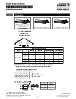
TO DETERMINE

HAND OF

YOUR DOOR:

LEFT
HAND
DOOR

RIGHT
HAND
DOOR

RHR

LHR

1

Introduction

L

3/8

(10)

1/4-20 THREAD

Drill thru 9/32 (7.1) Enlarge to

3/8 (9.5) Dia. This Side Only

(4 Places)

DOOR

THICKNESS

SEX NUT

LENGTH “L”

1-3/8" (35mm)

1--3/4" (44mm)

& OVER

1-9/32" (33mm)

1-21/32" (42mm)

MOUNTING SCREW SPECIFICATIONS

ARM AND CLOSER BRACKET

}

or

{

Option M54:
Sex nuts, furnished
when ordered

1/4-20 oval head machine
screw or 1/4-14 self-drilling
screw Type BSD. 3/16 (4.8)
diameter pilot hole required
for Wood Applications.

Figure 1 

A4 Arm

Non-Hold Open with Backstop

A5 Arm

A2 Arm

Hold Open with Backstop

*This application requires an

auxiliary door stop “by others”

Hold Open Only

(No Stop Feature)

Содержание DC3210 Series

Страница 1: ... product warranty To avoid personal injury DO NOT DISASSEMBLE THIS DOOR CLOSER BODY Door closers must be securely fastened to a properly reinforced door and frame with fasteners provided Door closers with a HOLD OPEN ARM are not permitted to be installed in fire door assemblies Door and frame must be specifically templated for 85 90 95 100 105 orb 110 door swing For installation assistance contact...

Страница 2: ... 5 24 4 6 4 0 6 26 TO DETERMINE HAND OF YOUR DOOR LEFT HAND DOOR RIGHT HAND DOOR RHR LHR 1 Introduction L 3 8 10 1 4 20 THREAD Drill thru 9 32 7 1 Enlarge to 3 8 9 5 Dia This Side Only 4 Places DOOR THICKNESS SEX LENG 1 3 8 35mm 1 3 4 44mm OVER 1 9 32 1 21 32 MOUNTING SCREW SPECIFICATIONS ARM AND CLOSER BRACKET or Option M54 Sex nuts furnished when ordered 1 4 20 oval head machine screw or 1 4 14 ...

Страница 3: ...Left Hand Opposite Dimensions given in inches mm Do Not Scale Drawing Closer must be installed in a true horizontal plane to ensure proper closer performance Figure 2 Opening Maximum DIM A DIM B DIM C Minimum 85 13 3 4 349 12 9 16 319 28 3 4 730 90 12 13 16 325 11 5 8 295 27 7 8 708 100 11 1 4 286 10 1 16 256 26 1 4 667 110 9 15 16 252 8 3 4 222 25 635 5 8 16 2 5 8 60 FRAME STOP TOP OF DOOR C L HI...

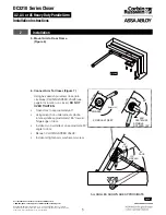
Страница 4: ...Corbin Russwin 1 800 543 3658 techsupport corbinrusswin assaabloy com Pin Hole End Countersunk Holes Holding Pins 1 4 20 x 1 2 OHMS 2 2 Installation 2 Install Closer Bracket Figure 3 Figure 3 3 Mount Closer Body to Closer Bracket Figure 4 4 A4 A5 Backstop Arms Only Arms shipped for Left Hand Door To change handing Figure 5 Remove Stop from Soffit with 5 32 Allen Wrench Remove Filler Plug Switch St...

Страница 5: ...2 OHMS 2 Figure 6 2 Installation 5 Mount Arm to Door Frame Figure 6 6 Connect Arm To Closer Figure 7 Using hex wrench provided close turn clockwise CLOSING SPEED VALVE see page 5 for location on closer DO NOT OVER TIGHTEN Open door to approximately 60 Using wrench on underside of spindle rotate spindle approximately 135 toward hinge edge of door Install arm on spindle at an approximate 90 angle to...

Страница 6: ...d LATCHING speeds to between 3 and 7 seconds Use of door by handicapped elderly or small children may require even greater closing time Backcheck Intensity Valve Figure 9 Turn valve COUNTER CLOCKWISE to reduce backcheck or CLOCKWISE to increase backcheck Backcheck should be set to give a soft cushioning action not a sudden stop Delayed Action Valve Figure 9 Turn valve CLOCKWISE to SLOW closing COU...

Страница 7: ...e 3 Full Cover Standard Slim Cover Option M76 Figure 12 Figure 13 Size of Door No of Full 360 Turns Clockwise of Power Adjuster Equivalent Closer Size Approx Interior Exterior In Swinging Exterior Out Swinging 2 4 712 2 6 764 4 2 2 6 764 3 0 915 8 3 3 0 915 3 6 1067 2 6 764 12 4 3 6 1067 4 0 1219 3 0 915 16 5 Figure 14 4 Cover Installation Full Cover Standard Slim Cover Option M76 Install Cover Fi...

Страница 8: ...ithout the express written permission of Corbin Russwin Inc is prohibited Patent pending and or patent www assaabloydss com patents Corbin Russwin 225 Episcopal Road Berlin CT 06037 Phone 800 543 3658 Fax 800 447 6714 corbinrusswin com For installation assistance contact Corbin Russwin 1 800 543 3658 techsupport corbinrusswin assaabloy com ...

Отзывы: