


ASSA ABLOY Scandinavia
Document ID
Revision
Date
Document Category
Page (of)
D001053357
2
2020-12-04
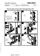
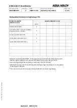
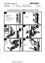
Assembly instruction
8 (12)
©
A
SS
A
AB
LO
Y
,
All
r
ig
h
ts
res
er
ved
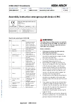
On double door sets with rebated meeting stiles
and where both leaves are fitted with panic exit
devices, it is essential to check that either leaf
will open when its panic exit device is activated
and also that both leaves will open freely when
both exit devices are operated simultaneously.
Where emergency exit devices are to be fitted
to double door sets with rebated meeting stiles
and self-closing devices, a door coordinator
device in accordance with EN 1158 should be
fitted to ensure the correct closing sequence of
the doors. This recommendation is particularly
important with regard to fire/smoke resisting
door assemblies. The use of a carry bar to move
the active leaf may be required for this
application e.g. ASSA 2010.
The minimum recommended width of the
passive door leaf on a double door set is 500
mm.
If a door closing device is to be used to return
the door to the closed position, care should be
taken not to impair the use of the doorway by
the young, elderly and infirm.
Category 2 (standard projection <100 mm)
emergency exit devices should be used in
situations where there is restricted width for
escape, or where the doors to be fitted with exit
devices are not able to open beyond 90°. Keep
in mind that mounting of e.g. pulling handles
also may affect the effective door opening
width, which should be considered if the door
has a limited opening angle.
No devices for securing the door in the closed
position should be fitted other than that
specified in these instructions. This does not
preclude the installation of self closing devices.
Exceptions may be made if national building
regulations permit this.
A sign which reads "Rotate to open" or a
pictogram should be provided on the inside face
of the door immediately above the operating
element, or on the operating element if it has a
sufficient flat face to take the size of lettering
required. The surface area of the pictogram
should be not less than 8 000 mm² and its colors
should be white on a green background. It
should be designed such that the arrow points
to the operating element, when installed. This
pictogram is not included in the package.
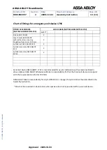
The supplied screws, which are not through-
door bolts, are recommended to be attached to
the following materials and thicknesses:
o
Steel minimum 2 mm or alternate with
M5 pop nuts
o
Aluminum minimum 4 mm or alternate
with M5 pop nuts
o
Wood minimum 20 mm
During installation:
Follow instructions on page 9.
After installation:
Lubricate all of the surfaces on the emergency
exit device and lock case with ASSA lock grease.
Make sure that any seals or weather-stripping
fitted to the complete door assembly, does not
inhibit the correct operations of the emergency
exit device.
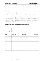
Measure opening forces. Results shall be
recorded and handed over to the end user.
Check any re-entrance function.
After completion of installation, the installer
shall provide the end user with documentation
such as installation and maintenance
instructions.
Approved
2020-12-04


