


English
24
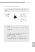
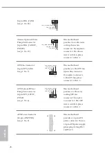
Power LED and Speaker
Header
(7-pin SPK_PLED1)
(see p.1, No. 16)
Please connect the
chassis power LED and
the chassis speaker to this
header.
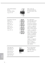
Serial ATA3 Connectors
(SATA3_0_1:
see p.1, No. 12)
(SATA3_2_3:
see p.1, No. 13)
(SATA3_4_5:
see p.1, No. 14)
(SATA3_6_7:
see p.1, No. 15)
These eight SATA3
connectors support SATA
data cables for internal
storage devices with up to
6.0 Gb/s data transfer rate.
* If M2_1 is occupied by
a SATA-type M.2 device,
SATA3_0 will be disabled.
* If M2_2 is occupied by
a SATA-type M.2 device,
SATA3_1 will be disabled.
* If M2_3 is occupied by
a SATA-type M.2 device,
SATA3_4 and SATA3_5
will be disabled.
* If M2_3 is occupied by
a PCIe-type M.2 device,
SATA3_4, SATA3_5,
SATA3_6 and SATA3_7
will be disabled.
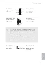
USB 2.0 Headers
(9-pin USB_5_6)
(see p.1, No. 22)
(9-pin USB_7_8)
(see p.1, No. 21)
(9-pin USB_9_10)
(see p.1, No. 20)
There are three headers
on this motherboard.
Each USB 2.0 header can
support two ports.
1
+5V
DUMMY
PLED+
PLED+
PLED-
DUMMY
SPEAKER
SA
T
A3_2
SA
T
A3_3
SA
T
A3_4
SA
T
A3_5
SA
T
A3_6
SA
T
A3_7
SA
T
A3_0
SA
T
A3_1
DUMMY
GND
GND
P+
P-
USB_PWR
P+
P-
USB_PWR
1


