background image

English

40

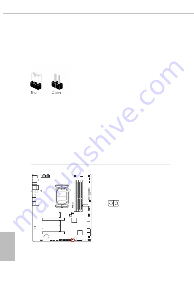
2.11  Jumpers Setup

The illustration shows how jumpers are setup. When the jumper cap is placed on 
the pins, the jumper is “Short”. If no jumper cap is placed on the pins, the jumper is 
“Open”. 

Clear CMOS Jumper 
(CLRCMOS1) (see p.7, No. 25)
CLRCMOS1 allows you to clear the data in CMOS. The data in CMOS includes 
system setup information such as system password, date, time, and system setup 
parameters. To clear and reset the system parameters to default setup, please 
turn off the computer and unplug the power cord, then use a jumper cap to short 
the pins on CLRCMOS1 for 3 seconds. Please remember to remove the jumper 
cap after clearing the CMOS. If you need to clear the CMOS when you just finish 
updating the BIOS, you must boot up the system first, and then shut it down 
before you do the clear-CMOS action.

X

6

7

O

T

a

ic

h

i C

a

r

r

a

r

a

2-pin Jumper

Short: Clear CMOS 
Open: Default

CLRCMOS1

Содержание Taichi Carrara X670E

Страница 1: ......

Страница 2: ... com or you may contact your dealer for further information For technical questions please submit a support request form at https event asrock com tsd asp ASRock Incorporation e mail info asrock com tw ASRock EUROPE B V e mail sales asrock nl ASRock America Inc e mail sales asrockamerica com Scan the QR code to view more manuals and documents ...

Страница 3: ...ngle USB Bracket 13 1 8 12CM Carrara Edition Cooling FAN 14 Chapter 2 Installation 16 2 1 Installing the CPU 17 2 2 Installing the CPU Fan and Heatsink 20 2 3 Installing Memory Modules DIMM 29 2 4 Connecting the Front Panel Header 31 2 5 Installing the Motherboard 32 2 6 Installing SATA Drives 33 2 7 Installing a Graphics Card 35 2 8 Connecting Peripheral Devices 37 2 9 Connecting the Power Connec...

Страница 4: ...and Connectors 41 2 13 Smart Switches 55 2 14 Dr Debug 59 2 15 M 2 SSD Module Installation Guide M2_1 65 2 16 M 2 SSD Module Installation Guide M2_2 70 2 17 M 2 SSD Module Installation Guide M2_3 73 2 18 M 2 SSD Module Installation Guide M2_4 76 ...

Страница 5: ...n5 Fan Heatsink Optional 1 x 12CM Carrara Edition Cooling FAN Optional 1 x ASRock WiFi 2 4 5 6 GHz Antenna Optional 4 x Screws for M 2 Sockets Optional 1 x Standoff for M 2 Socket Optional Because the motherboard specifications and the BIOS software might be updated the content of this documentation will be subject to change without notice In case any modi fications of this documentation occur the...

Страница 6: ...ing EXPO memory modules Please refer to Memory Support List on ASRock s website for more information http www asrock com Expansion Slot CPU 2 x PCIe 5 0 x16 Slots PCIE1 and PCIE2 support x16 or x8 x8 modes Chipset 1 x Vertical M 2 Socket Key E supports type 2230 WiFi BT PCIe WiFi module Supports NVMe SSD as boot disks Supports AMD CrossFireTM 15μ Gold Contact in VGA PCIe Slot PCIE1 Graphics Integr...

Страница 7: ... s Killer E3100G Supports Killer LAN Software Supports Killer DoubleShotTM Pro Wireless LAN 802 11ax Wi Fi 6E Module Supports IEEE 802 11a b g n ac ax Supports Dual Band 2x2 160MHz with extended 6GHz band support Wi Fi 6E 6GHz band will be supported by Microsoft Win dows 11 The availability will depend on the different regula tion status of each country and region It will be activated for supporte...

Страница 8: ...one Input Jack Gold Audio Jack Supports USB PD 3 0 up to 9V 3A 27W 5V 3A 15W charging Storage CPU 1 x Blazing M 2 Socket M2_1 Key M supports type 2280 PCIe Gen5x4 128 Gb s mode Chipset 1 x Hyper M 2 Socket M2_2 Key M supports type 2230 2242 2260 2280 22110 SATA3 6 0 Gb s PCIe Gen4x4 64 Gb s modes 1 x Hyper M 2 Socket M2_3 Key M supports type 2280 PCIe Gen4x4 64 Gb s mode 1 x Hyper M 2 Socket M2_4 ...

Страница 9: ...er Connectors Hi Density Power Connector 1 x Front Panel Audio Connector 15μ Gold Audio Connector 2 x USB 2 0 Headers Support 4 USB 2 0 ports 2 x USB 3 2 Gen1 Headers Support 4 USB 3 2 Gen1 ports 1 x Front Panel Type C USB 3 2 Gen2x2 Header 20 Gb s 1 x Dr Debug with LED 1 x Power Button with LED 1 x Reset Button with LED Supports in total up to 12V 3A 36W LED Strip Support in total up to 5V 3A 15W...

Страница 10: ...sting the setting in the BIOS applying Untied Overclocking Technology or using third party overclocking tools Overclocking may affect your system s stability or even cause damage to the components and devices of your system It should be done at your own risk and expense We are not responsible for possible damage caused by overclocking For detailed product information please visit our website http ...

Страница 11: ..._TC_1 2 6 4 DDR5_A2 64 bit 288 pin module DDR5_A1 64 bit 288 pin module DDR5_B2 64 bit 288 pin module DDR5_B1 64 bit 288 pin module 1 22 ATX12V2 5 7 SATA3_4 SATA3_3 SATA3_2 SATA3_1 SATA3_A4 SATA3_A3 SATA3_A2 SATA3_A1 15 19 CMOS Battery CHA_FAN5 WP RGB_LED1 1 ADDR_LED1 1 1 USB32_9_10 CLRCMOS1 1 CHA_FAN4 WP CHA_FAN3 WP AUDIO CODEC LAN CT7 CT8 CT9 CT10 CT11 CT5 M2_4 M2_2 CT3 M2_3 23 24 25 26 27 28 29...

Страница 12: ...er USB32_TC_1 14 Chassis Water Pump Fan Connector CHA_FAN6 WP 15 SATA3 Connectors SATA3_A2 Upper SATA3_A1 Lower 16 SATA3 Connectors SATA3_A4 Upper SATA3_A3 Lower 17 SATA3 Connectors SATA3_2 Upper SATA3_1 Lower 18 SATA3 Connectors SATA3_4 Upper SATA3_3 Lower 19 Power LED and Speaker Header SPK_PLED1 20 System Panel Header PANEL1 21 Power Button PWRBTN1 22 Reset Button RSTBTN1 23 Chassis Water Pump ...

Страница 13: ...t USB32_3 3 Microphone Input Jack 10 USB4 Type C Port 4 Line Out Jack 11 Optical SPDIF Out Port 5 USB 3 2 Gen1 Type A Ports 12 USB 3 2 Gen2 Type A Ports USB32_56 USB32_12 6 USB 3 2 Gen2 Type A Ports 13 HDMI Port USB32_78 14 Antenna Ports 7 USB 3 2 Gen1 Type A Port USB32_4 15 Clear CMOS Button 8 USB4 Type C Port 15 9 11 12 14 4 5 1 3 6 10 7 8 13 2 ...

Страница 14: ...onnection On Link Green 2 5Gbps connection Function of the Audio Ports in 2 4 or 5 1 channel Configuration Channel Port Function 2ch Line Out Jack Rear Panel Front speaker out 4ch Pink Mic Front Panel Rear speaker out 5 1ch Microphone Input Jack Rear Panel Central Subwoofer speaker out Ultra USB Power is supported on USB32_3 port ACPI wake up function is not supported on USB32_3 port USB32_12 are ...

Страница 15: ...M 2_2 PCIe x4 SATA x4 M 2_3 PCIe x4 Gen4 x4 Front USB 3 2 Gen2x2 Type C x4 Front USB 3 2 Gen1 2 ports Support BIOS Update Realtek ALC4082 I2S ESS 9218 DAC USB3 2 G1 ASM1061 SATA3_A2 SATA3_A1 SATA 6Gb s Quick Switch x1 ASM1061 SATA3_A4 SATA3_A3 SATA 6Gb s x1 WiFi key E x1 Intel Killer E3100G USB3 2 G2x2 10Gb s USB3 2 G2 5Gb s 480Mb s 480Mb s USB2 0 USB2 0 PCIe GEN4 PCIe GEN4 M 2_4 PCIe x4 Gen4 SATA...

Страница 16: ...atures Smart Ready technology that adds a whole new class of functionality into the mobile devices BT also includes Low Energy Technology and ensures extraordinary low power consumption for PCs The transmission speed may vary according to the environment Wi Fi 6E 6GHz band will be supported by Microsoft Windows 11 The availability will depend on the different regulation status of each country and ...

Страница 17: ...ireless Dongle USB Bracket Step 1 Plug the Wireless Dongle USB Bracket into the USB 2 0 header on your motherboard Step 2 Now you have two external USB 2 0 ports at hand We recommend you plugging wireless devices dongle into these USB 2 0 ports for the best wireless signal quality ...

Страница 18: ...e the 12CM Carrara Edition Cooling FAN to the rear of your PC case with screw holes aligned Then secure it with 4 screws Step 2 Plug the attached fan cable to a free fan connector on the motherboard Before installing the cooling fan please make sure that your motherboard is properly installed into a PC case ...

Страница 19: ... mmAq Airflow 76 21 CFM Rated Current AT 25 C 0 35 A Duty cycle 100 Rated Power AT 25 C 4 2 W Duty cycle 100 Sound Level 43 8 dB A MAX 46 8dBA Operation Voltage DC 6 0V 13 2V Start Up Voltage DC 6 0V 25 C Power ON OFF Duty cycle 100 Operating Temperature Range 10 C 70 C Storage Temperature Range 40 C 70 C Operating Staorage Humidity 5 90 RH ...

Страница 20: ... physical injuries and damages to motherboard components In order to avoid damage from static electricity to the motherboard s components NEVER place your motherboard directly on a carpet Also remember to use a grounded wrist strap or touch a safety grounded object before you handle the components Hold components by the edges and do not touch the ICs Whenever you uninstall any components place the...

Страница 21: ...e socket if the CPU surface is unclean or if there are any bent pins in the socket Do not force to insert the CPU into the socket if above situation is found Otherwise the CPU will be seriously damaged 2 Unplug all power cables before installing the CPU Tutorial Video Turn your CPU to the correct orientation before opening the CPU socket cover ...

Страница 22: ...English 18 Carefully place the CPU in as flat as possible Do not drop it 4 1 2 A B 3 ...

Страница 23: ...cessor is removed The cover must be placed if you wish to return the motherboard for after service Make sure the black cover plate is always in place until it pops off when closing the socket lever Make sure the CPU is aligned with the socket before locking it into place ...

Страница 24: ... cooling fan to dissipate heat You also need to spray thermal grease between the CPU and the heatsink to improve heat dissipation Make sure that the CPU and the heatsink are securely fastened and in good contact with each other Installing the CPU Cooler Type 1 Please turn off the power or remove the power cord before changing a CPU or heatsink 2 1 ...

Страница 25: ...English 21 X670E Taichi Carrara 4 3 C P U _ F A N 1 ...

Страница 26: ...English 22 Installing the CPU Cooler Type 2 2 1 ...

Страница 27: ...English 23 X670E Taichi Carrara 3 4 C P U _ F A N 1 ...

Страница 28: ...English 24 5 C P U _ F A N 1 RG B_LED1 The illustrations shown here are for reference purposes only and may not exactly match the model you purchase 12V ...

Страница 29: ...English 25 X670E Taichi Carrara Installing the CPU Cooler Type 3 2 1 ...

Страница 30: ...English 26 4 3 ...

Страница 31: ...English 27 X670E Taichi Carrara 5 C P U _ F A N 1 ...

Страница 32: ...hould be used at a time in this step If you select RGB_LED1 please install ASRock utility ASRock Polychrome SYNC If you select USB connector please install AMD utility SR3 Settings Software The illustrations shown here are for reference purposes only and may not exactly match the model you purchase 12V or ...

Страница 33: ...dual channel configuration you always need to install identical the same brand speed size and chip type DDR5 DIMM pairs 2 It is unable to activate Dual Channel Memory Technology with only one or three memory module installed 3 It is not allowed to install a DDR DDR2 DDR3 or DDR4 memory module into a DDR5 slot otherwise this motherboard and DIMM may be damaged 4 The DIMM only fits in one correct or...

Страница 34: ...English 30 1 2 3 ...

Страница 35: ... 2 4 Connecting the Front Panel Header A B C D 1 2 32 5 6 5 6 7 6 3 2 5 3 2 5 3 1 Power SW RESET SW HDD LED HDD LED 1 2 9 10 RESET SW Power SW Power LED Power LED A B C D PANEL1 HDD LED RESET SW System Panel Header Front Panel Wires ...

Страница 36: ...English 32 2 5 Installing the Motherboard ...

Страница 37: ...English 33 X670E Taichi Carrara 2 6 Installing SATA Drives 1 2 Optical Drive SATA Drive SATA Data Cable ...

Страница 38: ...English 34 3 4 SATA Power Connector SATA Data Connector ...

Страница 39: ...English 35 X670E Taichi Carrara 2 7 Installing a Graphics Card 1 CLICK ...

Страница 40: ...xpansion card please make sure that the power supply is switched off or the power cord is unplugged Please read the documentation of the expansion card and make necessary hardware settings for the card before you start the installation For a better thermal environment please connect a chassis fan to the motherboard s chassis fan connector CHA_FAN1 6 WP when using multiple graphics cards PCIE1 PCIE...

Страница 41: ...English 37 X670E Taichi Carrara 2 8 Connecting Peripheral Devices ...

Страница 42: ...English 38 2 9 Connecting the Power Connectors 7 3 5 7 9 ...

Страница 43: ...English 39 X670E Taichi Carrara 2 10 Power On 2 3 4 1 ...

Страница 44: ...ch as system password date time and system setup parameters To clear and reset the system parameters to default setup please turn off the computer and unplug the power cord then use a jumper cap to short the pins on CLRCMOS1 for 3 seconds Please remember to remove the jumper cap after clearing the CMOS If you need to clear the CMOS when you just finish updating the BIOS you must boot up the system...

Страница 45: ...ing the power button RESET Reset Button Connect to the reset button on the chassis front panel Press the reset button to restart the computer if the computer freezes and fails to perform a normal restart PLED System Power LED Connect to the power status indicator on the chassis front panel The LED is on when the system is operating The LED keeps blinking when the system is in S1 S3 sleep state The...

Страница 46: ... 42 Power LED and Speaker Header 7 pin SPK_PLED1 see p 7 No 19 Please connect the chassis power LED and the chassis speaker to this header X67OE Taichi Carrara 1 5V DUMMY PLED PLED PLED DUMMY SPEAKER SPK_PLED1 ...

Страница 47: ... 7 No 15 Upper SATA3_A3 see p 7 No 16 Lower SATA3_A4 see p 7 No 16 Upper These eight SATA3 connectors support SATA data cables for internal storage devices with up to 6 0 Gb s data transfer rate To minimize the boot time use AMD SATA ports SATA3_1 4 for your SSDs If M2_2 is occupied by a SATA type M 2 device SATA3_A1 will be disabled X67OE Taichi Carrara SATA3_2 SATA3_4 SATA3_A4 SATA3_1 SATA3_3 SA...

Страница 48: ...see p 7 No 28 9 pin USB_3_4 see p 7 No 27 There are two headers on this motherboard Each USB 2 0 header can support two ports X67OE Taichi Carrara DUMMY GND GND P P USB_PWR P P USB_PWR 1 USB_1_2 DUMMY GND GND P P USB_PWR P P USB_PWR 1 USB_3_4 ...

Страница 49: ...two ports X67OE Taichi Carrara 1 IntA_PB_D Dummy IntA_PB_D GND IntA_PB_SSTX GND IntA_PB_SSTX IntA_PB_SSRX IntA_PB_SSRX Vbus Vbus Vbus IntA_PA_SSRX IntA_PA_SSRX GND IntA_PA_SSTX IntA_PA_SSTX GND IntA_PA_D IntA_PA_D USB32_11_12 1 ID IntA_P_D IntA_P_D GND IntA_P_SSTX IntA_P_SSTX GND IntA_P_SSRX Vbus IntA_P_D IntA_P_D GND IntA_P_SSTX IntA_P_SSTX GND IntA_P_SSRX IntA_P_SSRX Vbus IntA_P_SSRX USB32_9_10 ...

Страница 50: ...r 20 pin USB32_TC_1 see p 7 No 13 There is one Front Panel Type C USB 3 2 Gen2x2 Header on this motherboard This header is used for connecting a USB 3 2 Gen2x2 module for additional USB 3 2 Gen2x2 ports X67OE Taichi Carrara USB32_TC_1 USB Type C Cable ...

Страница 51: ...s to the front audio panel X67OE Taichi Carrara J_SENSE OUT2_L 1 MIC_RET PRESENCE GN D OUT2_R MIC2_R MIC2_L OUT_RET HD_AUDIO1 High Definition Audio supports Jack Sensing but the panel wire on the chassis must sup port HDA to function correctly Please follow the instructions in our manual and chassis manual to install your system ...

Страница 52: ...f you plan to connect a 3 Pin chassis water cooler fan please connect it to Pin 1 3 X67OE Taichi Carrara CHA_FAN3 WP GND CHA_FAN_SPEED FAN_SPEED_CONTROL FAN_VOLTAGE 1 2 3 4 CHA_FAN2 WP CHA_FAN4 WP GND CHA_FAN_SPEED FAN_SPEED_CONTROL FAN_VOLTAGE 1 2 3 4 CHA_FAN5 WP GND CHA_FAN_SPEED FAN_SPEED_CONTROL FAN_VOLTAGE 1 2 3 4 CHA_FAN6 WP GND CHA_FAN_SPEED FAN_SPEED_CONTROL FAN_VOLTAGE 1 2 3 4 CHA_FAN1 WP...

Страница 53: ...it to Pin 1 3 X67OE Taichi Carrara CPU Water Pump Fan Connector 4 pin CPU_FAN2 WP_3A see p 7 No 6 This motherboard provides a 4 Pin water cooling CPU fan connector If you plan to connect a 3 Pin CPU water cooler fan please connect it to Pin 1 3 X67OE Taichi Carrara CPU_FAN1 CPU_F 12V GND AN_SPEED FAN_SPEED_CONTROL 4 3 2 1 CPU_FAN2 WP_3A CPU_F FAN_VOLTAGE GND AN_SPEED FAN_SPEED_CONTROL 4 3 2 1 ...

Страница 54: ...TX Power Connector 24 pin ATXPWR1 see p 7 No 10 This motherboard provides a 24 pin ATX power connector To use a 20 pin ATX power supply please plug it along Pin 1 and Pin 13 X67OE Taichi Carrara ATXPWR1 12 1 24 13 ...

Страница 55: ...TX 12V power connectors To use a 4 pin ATX power supply please plug it along Pin 1 and Pin 5 Connecting an ATX 12V 8 pin cable to ATX12V2 is optional Warning Please make sure that the power cable connected is for the CPU and not the graphics card Do not plug the PCIe power cable to this connector X67OE Taichi Carrara ATX12V2 ATX12V1 4 1 8 5 4 1 8 5 ...

Страница 56: ...orientation otherwise the cable may be damaged 2 Before installing or removing your RGB LED cable please power off your system and unplug the power cord from the power supply Failure to do so may cause dam ages to motherboard components 1 Please note that the RGB LED strips do not come with the package 2 The RGB LED header supports standard 5050 RGB LED strip 12V G R B with a maximum power rating ...

Страница 57: ...ble LED extension cables which allow users to choose from various LED lighting effects Caution Never install the Addressable LED cable in the wrong orientation otherwise the cable may be damaged X67OE Taichi Carrara VOUT DO_ADDR GND 1 ADDR_LED1 ADDR_LED3 ADDR_LED2 1 Connect your Addressable RGB LED strips to the Addressable LED Headers ADDR_ LED1 ADDR_LED2 ADDR_LED3 on the motherboard ...

Страница 58: ... cable please power off your system and unplug the power cord from the power supply Failure to do so may cause damages to motherboard components 1 Please note that the RGB LED strips do not come with the package 2 The RGB LED header supports WS2812B addressable RGB LED strip 5V Data GND with a maximum power rating of 3A 5V and length within 2 meters ...

Страница 59: ...utton allowing users to quickly turn on off the system reset the system clear the CMOS values or flash the BIOS Power Button PWRBTN1 see p 7 No 21 Power Button allows users to quickly turn on off the system X67OE Taichi Carrara Reset Button RSTBTN1 see p 7 No 22 Reset Button allows users to quickly reset the system X67OE Taichi Carrara RSTBTN1 PWRBTN1 Reset ...

Страница 60: ...CMOS Button CLRCMOS see p 9 No 15 Clear CMOS Button allows users to quickly clear the CMOS values X67OE Taichi Carrara CLRCMOS This function is workable only when you power off your computer and unplug the power supply ...

Страница 61: ...English 57 X670E Taichi Carrara BIOS Flashback Button BIOS_FB see p 9 No 1 BIOS Flashback Button allows users to flash the BIOS X67OE Taichi Carrara BIOS_FB USB BIOS Flashback port ...

Страница 62: ...t three seconds Then the LED starts to blink 8 Wait until the LED stops blinking indicating that BIOS flashing has been completed If the LED light turns solid green this means that the BIOS Flashback is not operating properly Please make sure that you plug the USB drive to the USB BIOS Flashback port If the LED does not light up at all then please disconnect power from the system and remove discon...

Страница 63: ...r Debug codes Code Description 0x10 PEI_CORE_STARTED 0x11 PEI_CAR_CPU_INIT 0x15 PEI_CAR_NB_INIT 0x19 PEI_CAR_SB_INIT 0x31 PEI_MEMORY_INSTALLED 0x32 PEI_CPU_INIT 0x33 PEI_CPU_CACHE_INIT 0x34 PEI_CPU_AP_INIT 0x35 PEI_CPU_BSP_SELECT 0x36 PEI_CPU_SMM_INIT 0x37 PEI_MEM_NB_INIT 0x3B PEI_MEM_SB_INIT 0x4F PEI_DXE_IPL_STARTED 0x60 DXE_CORE_STARTED 0x61 DXE_NVRAM_INIT 0x62 DXE_SBRUN_INIT ...

Страница 64: ..._SB_SMM_INIT 0x72 DXE_SB_DEVICES_INIT 0x78 DXE_ACPI_INIT 0x79 DXE_CSM_INIT 0x90 DXE_BDS_STARTED 0x91 DXE_BDS_CONNECT_DRIVERS 0x92 DXE_PCI_BUS_BEGIN 0x93 DXE_PCI_BUS_HPC_INIT 0x94 DXE_PCI_BUS_ENUM 0x95 DXE_PCI_BUS_REQUEST_RESOURCES 0x96 DXE_PCI_BUS_ASSIGN_RESOURCES 0x97 DXE_CON_OUT_CONNECT 0x98 DXE_CON_IN_CONNECT ...

Страница 65: ...CT 0x9D DXE_USB_ENABLE 0xA0 DXE_IDE_BEGIN 0xA1 DXE_IDE_RESET 0xA2 DXE_IDE_DETECT 0xA3 DXE_IDE_ENABLE 0xA4 DXE_SCSI_BEGIN 0xA5 DXE_SCSI_RESET 0xA6 DXE_SCSI_DETECT 0xA7 DXE_SCSI_ENABLE 0xA8 DXE_SETUP_VERIFYING_PASSWORD 0xA9 DXE_SETUP_START 0xAB DXE_SETUP_INPUT_WAIT 0xAD DXE_READY_TO_BOOT 0xAE DXE_LEGACY_BOOT ...

Страница 66: ...OM_INIT 0xB3 DXE_RESET_SYSTEM 0xB4 DXE_USB_HOTPLUG 0xB5 DXE_PCI_BUS_HOTPLUG 0xB6 DXE_NVRAM_CLEANUP 0xB7 DXE_CONFIGURATION_RESET 0xF0 PEI_RECOVERY_AUTO 0xF1 PEI_RECOVERY_USER 0xF2 PEI_RECOVERY_STARTED 0xF3 PEI_RECOVERY_CAPSULE_FOUND 0xF4 PEI_RECOVERY_CAPSULE_LOADED 0xE0 PEI_S3_STARTED 0xE1 PEI_S3_BOOT_SCRIPT 0xE2 PEI_S3_VIDEO_REPOST ...

Страница 67: ...INSTALLED 0x57 PEI_CPU_MISMATCH 0x58 PEI_CPU_SELF_TEST_FAILED 0x59 PEI_CPU_NO_MICROCODE 0x5A PEI_CPU_ERROR 0x5B PEI_RESET_NOT_AVAILABLE 0xD0 DXE_CPU_ERROR 0xD1 DXE_NB_ERROR 0xD2 DXE_SB_ERROR 0xD3 DXE_ARCH_PROTOCOL_NOT_AVAILABLE 0xD4 DXE_PCI_BUS_OUT_OF_RESOURCES 0xD5 DXE_LEGACY_OPROM_NO_SPACE 0xD6 DXE_NO_CON_OUT 0xD7 DXE_NO_CON_IN ...

Страница 68: ...0xD9 DXE_BOOT_OPTION_LOAD_ERROR 0xDA DXE_BOOT_OPTION_FAILED 0xDB DXE_FLASH_UPDATE_FAILED 0xDC DXE_RESET_NOT_AVAILABLE 0xE8 PEI_MEMORY_S3_RESUME_FAILED 0xE9 PEI_S3_RESUME_PPI_NOT_FOUND 0xEA PEI_S3_BOOT_SCRIPT_ERROR 0xEB PEI_S3_OS_WAKE_ERROR ...

Страница 69: ...replace mPCIe and mSATA The Blazing M 2 Socket M2_1 Key M supports type 2280 PCIe Gen5x4 128 Gb s mode Installing the M 2 SSD Module Step 1 Prepare a M 2 SSD module and the screw Step 2 Depending on the PCB type and length of your M 2 SSD module find the corresponding nut location to be used No 1 Nut Location A PCB Length 8cm Module Type Type2280 ...

Страница 70: ... on the bottom side of the M 2 heatsink before you install a M 2 SSD module Step 4 Align and gently insert the M 2 SSD module into the M 2 slot Please be aware that the M 2 SSD module only fits in one orientation Step 5 Tighten the screw that comes with the package with a screwdriver to secure the module into place A A 20o NUT1 NUT2 2 1 1 ...

Страница 71: ...the order shown Tighten screw opposite the M 2 connector first 2 and then tighten the one next to the M 2 connector 3 Please do not overtighten the screw as this might damage the module and M 2 heatsink For the latest updates of M 2 SSD module support list please visit our website for details http www asrock com 1 2 3 ...

Страница 72: ... replace the pre installed M 2 heatsink with Blazing M 2 Gen5 Fan Heatsink that comes with the package Step 1 Prepare a M 2 SSD module and the screw Step 2 Before installing a M 2 SSD module please loosen the screws to remove the pre installed M 2 heatsink Step 3 Align and gently insert the M 2 SSD module into the M 2 slot Please be aware that the M 2 SSD module only fits in one orientation 2 1 1 ...

Страница 73: ...ighten the screw with a screwdriver to secure Blazing M 2 Gen5 Fan Heatsink into place in the order shown Tighten screw opposite the M 2 connector first 2 and then tighten the one next to the M 2 connector 3 Please do not overtighten the screw as this might damage the module and M 2 heatsink Step 6 Plug the fan cable to a free fan connector on the motherboard NUT1 NUT2 1 2 3 Dimension 144 58 36 7 ...

Страница 74: ...PCIe Gen4x4 64 Gb s modes If M2_2 is occupied by a SATA type M 2 device SATA3_A1 will be disabled Installing the M 2 SSD Module Step 1 Prepare a M 2 SSD module and the screw 3 2 4 5 B C D E A 1 Step 2 Depending on the PCB type and length of your M 2 SSD module find the corresponding nut location to be used No 1 2 3 4 5 Nut Location A B C D E PCB Length 3cm 4 2cm 6cm 8cm 11cm Module Type Type2230 T...

Страница 75: ...SD module A B C D E 20o A B C D E Step 4 Prepare the M 2 standoff that comes with the package Then hand tighten the standoff into the desired nut location on the motherboard Align and gently insert the M 2 SSD module into the M 2 slot Please be aware that the M 2 SSD module only fits in one orientation NUT1 NUT2 D E Step 5 Tighten the screw that comes with the package with a screwdriver to secure ...

Страница 76: ...www asrock com 3 2 1 Step 6 Tighten the screw with a screwdriver to secure the M 2 heatsink into place in the order shown Tighten screw opposite the M 2 connector first 2 and then tighten the one next to the M 2 connector 3 Please do not overtighten the screw as this might damage the module and M 2 heatsink ...

Страница 77: ...o replace mPCIe and mSATA The Hyper M 2 Socket M2_3 Key M supports type 2280 PCIe Gen4x4 64 Gb s mode Installing the M 2 SSD Module Step 1 Prepare a M 2 SSD module and the screw Step 2 Depending on the PCB type and length of your M 2 SSD module find the corresponding nut location to be used No 1 Nut Location A PCB Length 8cm Module Type Type2280 ...

Страница 78: ...ve films on the bottom side of the M 2 heatsink before you install a M 2 SSD module Step 4 Align and gently insert the M 2 SSD module into the M 2 slot Please be aware that the M 2 SSD module only fits in one orientation Step 5 Tighten the screw that comes with the package with a screwdriver to secure the module into place A A 20o NUT1 NUT2 ...

Страница 79: ...for details http www asrock com Step 6 Tighten the screws with a screwdriver to secure the M 2 heatsink into place in the order shown Tighten screws opposite the M 2 connector first 2 and then tighten the ones next to the M 2 connector 3 Please do not overtighten the screw as this might damage the module and M 2 heatsink ...

Страница 80: ...PCIe and mSATA The Hyper M 2 Socket M2_4 Key M supports type 2280 PCIe Gen4x4 64 Gb s mode Installing the M 2 SSD Module Step 1 Prepare a M 2 SSD module and the screw Step 2 Depending on the PCB type and length of your M 2 SSD module find the corresponding nut location to be used No 1 Nut Location A PCB Length 8cm Module Type Type2280 ...

Страница 81: ...he protective films on the bottom side of the M 2 heatsink before you install a M 2 SSD module Step 4 Align and gently insert the M 2 SSD module into the M 2 slot Please be aware that the M 2 SSD module only fits in one orientation Step 5 Tighten the screw that comes with the package with a screwdriver to secure the module into place A A 20o NUT1 NUT2 ...

Страница 82: ...s http www asrock com Step 6 Tighten the screws with a screwdriver to secure the M 2 heatsink into place in the order shown Tighten screws opposite the M 2 connector first 2 and then tighten the ones next to the M 2 connector 3 Please do not overtighten the screw as this might damage the module and M 2 heatsink ...

Страница 83: ...s loss of business loss of data interruption of business and the like even if ASRock has been advised of the possibility of such damages arising from any defect or error in the documentation or product This device complies with Part 15 of the FCC Rules Operation is subject to the following two conditions 1 this device may not cause harmful interference and 2 this device must accept any interferenc...

Страница 84: ...ornia Legislature When you discard the Lithium battery in California USA please follow the related regulations in advance Perchlorate Material special handling may apply see www dtsc ca gov hazardouswaste perchlorate AUSTRALIA ONLY Our goods come with guarantees that cannot be excluded under the Australian Consumer Law You are entitled to a replacement or refund for a major failure and compensatio...

Страница 85: ...Rock disclose the relevant information based on regulation requirements Please refer to https www asrock com general about asp cat Responsibility for informa tion disclosure based on regulation requirements ASRock is complied with DO NOT throw the motherboard in municipal waste This product has been designed to enable proper reuse of parts and recycling This symbol of the crossed out wheeled bin i...

Страница 86: ...ransmit power per transceiver type Function Frequency Maximum Output Power EIRP WiFi 2400 2483 5 MHz 18 5 1 5 dbm 5150 5250 MHz 21 5 1 5 dbm 5250 5350 MHz 18 5 1 5 dbm no TPC 21 5 1 5 dbm TPC 5470 5725 MHz 25 5 1 5 dbm no TPC 28 5 1 5 dbm TPC Bluetooth 2400 2483 5 MHz 8 5 1 5 dbm ...

Отзывы: