background image

3 3

3 3

3 3

3 3

3 3

ASRock  

ALiveDual-eSATA2

  Motherboard

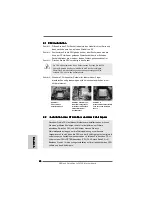
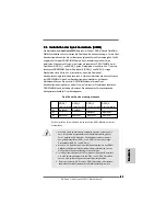
3. BIOS Information

3. BIOS Information

3. BIOS Information

3. BIOS Information

3. BIOS Information

The Flash Memory on the motherboard stores BIOS Setup Utility. When you start up

the computer, please press <F2> during the Power-On-Self-Test (POST) to enter

BIOS Setup utility; otherwise, POST continues with its test routines. If you wish to

enter BIOS Setup after POST, please restart the system by pressing <Ctl> + <Alt> +

<Delete>, or pressing the reset button on the system chassis. The BIOS Setup program

is designed to be user-friendly. It is a menu-driven program, which allows you to scroll

through its various sub-menus and to select among the predetermined choices. For the

detailed information about BIOS Setup, please refer to the User Manual (PDF file) con-

tained in the Support CD.

4. Software Suppor

4. Software Suppor

4. Software Suppor

4. Software Suppor

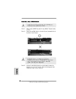
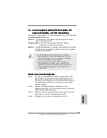
4. Software Support CD information

t CD information

t CD information

t CD information

t CD information

This motherboard supports various Microsoft

®

 Windows

®

 operating systems: 2000 /

XP / XP Media Center / XP 64-bit / Vista

TM

 / Vista

TM

 64-bit. The Support CD that came

with the motherboard contains necessary drivers and useful utilities that will en-

hance motherboard features. To begin using the Support CD, insert the CD into your CD-

ROM drive. It will display the Main Menu automatically if “AUTORUN” is enabled in your

computer. If the Main Menu does not appear automatically, locate and double-click on

the file “ASSETUP.EXE” from the “BIN” folder in the Support CD to display the menus.

EnglishEnglishEnglishEnglishEnglish

Содержание ALIVEDUAL-ESATA2

Страница 1: ...expressed or implied including but not limited to the implied warranties or conditions of merchantability or fitness for a particular purpose In no event shall ASRock its directors officers employees or agents be liable for any indirect special incidental or consequential damages including damages for loss of profits loss of business loss of data interruption of business and the like even if ASRoc...

Страница 2: ...7 2 x 240 pin DDRII DIMM Slots 24 Floppy Connector FLOPPY1 Dual Channel A DDRII_1 DDRII_2 Yellow 25 WiFi Header WIFI 8 2 x 240 pin DDRII DIMM Slots 26 JR1 JL1 Jumper Dual Channel B DDRII_3 DDRII_4 Orange 27 Front Panel Audio Header AUDIO1 9 Primary SATAII Connector SATAII_1 Red 28 PCI Slots PCI1 3 10 Secondary SATAII Connector 29 HDMI_SPDIF Header HDMI_SPDIF1 SATAII_2 Orange 30 Internal Audio Conn...

Страница 3: ...45 Port 10 USB 2 0 Ports USB01 4 Side Speaker Gray 11 USB 2 0 Ports USB23 5 Rear Speaker Black 12 eSATAII Port 6 Central Bass Orange 13 COM Port 7 Line In Light Blue 14 PS 2 Keyboard Port Purple If you use 2 channel speaker please connect the speaker s plug into Front Speaker Jack See the table below for connection details in accordance with the type of speaker you use TABLE for Audio Output Conne...

Страница 4: ...t notice In case any modifications of this manual occur the updated version will be available on ASRock website without further notice You may find the latest VGA cards and CPU support lists on ASRock website as well ASRock website http www asrock com If you require technical support related to this motherboard please visit our website for specific information about the model you are using www asr...

Страница 5: ...pportDDRII800 667 533 Max capacity 8GB see CAUTION 3 Hybrid Booster CPU Frequency Stepless Control see CAUTION 4 ASRock U COP see CAUTION 5 Boot Failure Guard B F G ASRock AM2 Boost ASRock Patented Technology to boost memory performance up to 12 5 see CAUTION 6 Expansion Slot 1 x PCI Express x16 slot 1 x AGP 8X slot see CAUTION 7 3 x PCI slots Audio 7 1 CH Windows VistaTM Premium Level Superior Au...

Страница 6: ...onnector 1 x IR header 1 x HDMI_SPDIF header CPU Chassis FAN connector 24 pin ATX power connector 4 pin 12V power connector CD in header Front panel audio connector 1 x USB 2 0 header supports 2 USB 2 0 ports see CAUTION 11 1 x WiFi header see CAUTION 12 BIOS Feature 4Mb AMI BIOS AMI Legal BIOS Supports Plug and Play ACPI 1 1 Compliance Wake Up Events Supports jumperfree SMBIOS 2 3 1 Support Suppo...

Страница 7: ...t overclocking technology If you enable this function in the BIOS setup the memory performance will improve up to 12 5 but the effect still depends on the AM2 CPU you adopt Enabling this function will overclock the chipset CPU reference clock However we can not guarantee the system stability for all CPU DRAM configurations If your system is unstable after AM2 Boost function is enabled it may not b...

Страница 8: ...ead eSATAII Interface Introduction on page 21 for details about eSATAII and eSATAII installation procedures 11 Power Management for USB 2 0 works fine under Microsoft Windows VistaTM 64 bit VistaTM XP 64 bit XP SP1 or SP2 2000 SP4 12 WiFi header supports WiFi AP function with ASRock WiFi 802 11g or WiFi 802 11n module an easy to use wireless local area network WLAN adapter It allows you to create ...

Страница 9: ...ny component ensure that the power is switched off or the power cord is detached from the power supply Failure to do so may cause severe damage to the motherboard peripherals and or components 1 Unplug the power cord from the wall socket before touching any component 2 To avoid damaging the motherboard components due to static electricity NEVER place your motherboard directly on the carpet or the ...

Страница 10: ...indicate that it is locked 2 2 2 2 2 2 2 2 2 2 Installation of CPU Fan and Heatsink Installation of CPU Fan and Heatsink Installation of CPU Fan and Heatsink Installation of CPU Fan and Heatsink Installation of CPU Fan and Heatsink After you install the CPU into this motherboard it is necessary to install a larger heatsink and cooling fan to dissipate heat You also need to spray thermal grease bet...

Страница 11: ...entical DDRII DIMMs in all four slots You may refer to the Dual Channel Memory Configuration Table below Dual Channel Memory Configurations DDRII_1 DDRII_2 DDRII_3 DDRII_4 Yellow Slot Yellow Slot Orange Slot Orange Slot 1 Populated Populated 2 Populated Populated 3 Populated Populated Populated Populated For the configuration 3 please install identical DDRII DIMMs in all four slots 1 If you want t...

Страница 12: ...omponents Step 1 Unlock a DIMM slot by pressing the retaining clips outward Step 2 Align a DIMM on the slot such that the notch on the DIMM matches the break on the slot The DIMM only fits in one correct orientation It will cause permanent damage to the motherboard and the DIMM if you force the DIMM into the slot at incorrect orientation Step 3 Firmly insert the DIMM into the slot until the retain...

Страница 13: ...se permanent damage For the voltage information of your AGP card please check with the AGP card vendors 2 If you plan to install Windows VistaTM 32 bit VistaTM 64 bit OS on this motherboard please read the instructions and limitation on page 169 and 170 carefully For Windows 2000 XP XP 64 bit OS there is no such limitation Installing an expansion card Installing an expansion card Installing an exp...

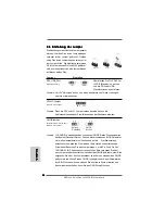
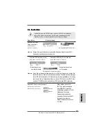
Страница 14: ...ndby current provided by power supply JR1 JL1 Jumper see p 2 No 26 Note If the jumpers JL1 and JR1 are short both the front panel and the rear panel audio connectors can work Clear CMOS Jumper CLRCMOS1 see p 2 No 16 Note CLRCMOS1 allows you to clear the data in CMOS The data in CMOS includes system setup information such as system password date time and system setup parameters To clear and reset t...

Страница 15: ..._2 connect the black end to the IDE devices connect the blue end to the motherboard 80 conductor ATA 66 100 133 cable 2 6 Onboard Headers and Connectors 2 6 Onboard Headers and Connectors 2 6 Onboard Headers and Connectors 2 6 Onboard Headers and Connectors 2 6 Onboard Headers and Connectors Floppy Connector 33 pin FLOPPY1 see p 2 No 24 Note Make sure the red striped side of the cable is plugged i...

Страница 16: ... 21 for details about eSATAII and eSATAII installation procedures eSATAII_TOP USB 2 0 Header Besides four default USB 2 0 9 pin USB4_5 ports on the I O panel there is see p 2 No 22 one USB 2 0 header on this motherboard This USB 2 0 header can support two USB 2 0 ports Serial ATA SATA Either end of the SATA data cable Data Cable can be connected to the SATA Optional SATAII hard disk or the SATAII ...

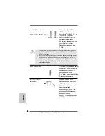
Страница 17: ... 5 pin IR1 wireless transmitting and see p 2 No 21 receiving infrared module Internal Audio Connectors This connector allows you 4 pin CD1 to receive stereo audio input CD1 see p 2 No 30 from sound sources such as a CD ROM DVD ROM TV tuner card or MPEG card Front Panel Audio Header This is an interface for the front 8 pin AUDIO1 panel audio cable that allows see p 2 No 27 convenient connection and...

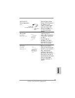
Страница 18: ...an ATX power 24 pin ATXPWR1 supply to this connector see p 2 No 33 ATX 12V Power Connector Please note that it is necessary 4 pin ATX12V1 to connect a power supply with see p 2 No 2 ATX 12V plug to this connector Failing to do so will cause power up failure HDMI_SPDIFHeader HDMI_SPDIF header providing 3 pin HDMI_SPDIF1 SPDIF audio output to HDMI VGA see p 2 No 29 card allows the system to con nect...

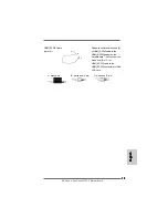
Страница 19: ...lish English C B A HDMI_SPDIFCable Please connect the black end A Optional of HDMI_SPDIF cable to the HDMI_SPDIF header on the motherboard Then connect the white end B or C of HDMI_SPDIF cable to the HDMI_SPDIF connector of HDMI VGA card A black end B white end 2 pin C white end 3 pin ...

Страница 20: ...IF connectors on HDMI VGA card please refer to the user manual of HDMI VGA card vendor Incorrect connection may cause permanent damage to this motherboard and the HDMI VGA card white end 2 pin B white end 3 pin C Please do not connect the white end of HDMI_SPDIF cable to the wrong connector of HDMI VGA card or other VGA card Otherwise the motherboard and the VGA card may be damaged For example thi...

Страница 21: ...B 2 0 is up to 480Mb s and for IEEE 1394 is up to 400Mb s However eSATAII provides the data transfer rate up to 3000Mb s which is much higher than USB 2 0 and IEEE 1394 and still keeps the convenience of Hot Plug feature Therefore on the basis of the advantageous transfer speed and the facilitating mobile capability in the near future eSATAII will replace USB 2 0 and IEEE 1394 to be a trend for ex...

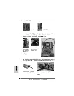
Страница 22: ...ce and the eSATAII port of the I O shield according to the eSATAII connector that you connect the SATA data cable Connect the SATA data cable to the orange SATAII connector SATAII_2 Connect the SATA data cable to the eSATAII connector eSATAII_TOP 1 In order to enable the eSATAII port of the I O shield you need to connect the orange SATAII connector SATAII_2 see p 2 No 10 and the eSATAII connector ...

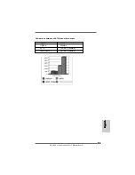
Страница 23: ... 3 2 3 ASRock ALiveDual eSATA2 Motherboard Comparison between eSATAII and other devices IEEE1394 400Mb s USB 2 0 480Mb s SATA 1 5Gb s 1500Mb s eSATAII SATAII 3 0Gb s 3000Mb s English English English English English ...

Страница 24: ...o SATAII mode in advance otherwise your SATAII hard disk may fail to run at SATAII mode Western Digital If pin 5 and pin 6 are shorted SATA 1 5Gb s will be enabled On the other hand if you want to enable SATAII 3 0Gb s please remove the jumpers from pin 5 and pin 6 SAMSUNG If pin 3 and pin 4 are shorted SATA 1 5Gb s will be enabled On the other hand if you want to enable SATAII 3 0Gb s please remo...

Страница 25: ...south bridge chipset that supports Serial ATA SATA hard disks and RAID functions You may install SATA SATAII hard disks on this motherboard for internal storage devices This section will guide you to install the SATA SATAII hard disks STEP 1 Install the SATA SATAII hard disks into the drive bays of your chassis STEP 2 Connect the SATA power cable to the SATA SATAII hard disk STEP 3 Connect one end...

Страница 26: ...ng interface for SATA host controllers developed thru a joint industry effort AHCI also provides usability enhancements such as Hot Plug NOTE What is Hot Plug Function If the SATA SATAII HDDs are NOT set for RAID configuration it is called Hot Plug for the action to insert and remove the SATA SATAII HDDs while the system is still power on and in working condition However please note that it cannot...

Страница 27: ...t we provide you with the following driver installation choices 1 All in 1 Logo Driver Without RAIDDriver You may choose this item to install all in 1 logo driver which does not support RAID functions but it has passed Microsoft logo certification 2 All in 1 Non Logo Driver With RAIDDriver You may choose this item to install all in 1 non logo driver which supports RAID functions but it has not pas...

Страница 28: ...Before installing Windows 2000 to your system your Windows 2000 optical disk is supposed to include SP4 If there is no SP4 included in your disk please visit below website for proper procedures of making a SP4 disk http www microsoft com Windows2000 downloads servicepacks sp4 spdeploy htm the_integrated_installation_fmay STEP 1 Set up BIOS A Enter BIOS SETUP UTILITY Advanced screen IDE Configurati...

Страница 29: ...a SATA SATAII driver diskette and set RAID configuration you can start to install Windows 2000 XP XP 64 bit on your system At the beginning of Windows setup press F6 to install a third party RAID driver When prompted insert the SATA SATAII driver diskette containing NVIDIA and JMicron RAID driver After reading the floppy disk the driver will be presented Select your required driver to install acco...

Страница 30: ... a SATAII driver diskette STEP 3 Use RAID Installation Guide to set RAID configuration Before you start to configure RAID function you need to check the RAID installation guide in the Support CD for proper configuration Please refer to the BIOS RAID installation guide of the document in the following path in the Support CD RAID Installation Guide STEP 4 Install Windows VistaTM VistaTM 64 bit OS on...

Страница 31: ... website for proper procedures of making a SP4 disk http www microsoft com Windows2000 downloads servicepacks sp4 spdeploy htm the_integrated_installation_fmay STEP 1 Set up BIOS A Enter BIOS SETUP UTILITY Advanced screen IDE Configuration B If you plan to install Windows 2000 XP XP 64 bit on NVIDIA SATA ports without RAID functions please set the SATA Operation Mode option to non RAID If you plan...

Страница 32: ...ATAII Operation Mode option to IDE or AHCI STEP 2 Install Windows VistaTM VistaTM 64bit OS on your system You can start to install Windows VistaTM VistaTM 64 bit on your system 2 15 2 15 2 15 2 15 2 15 Untied Overclocking T Untied Overclocking T Untied Overclocking T Untied Overclocking T Untied Overclocking Technology echnology echnology echnology echnology This motherboard supports Untied Overcl...

Страница 33: ...oices For the detailed information about BIOS Setup please refer to the User Manual PDF file con tained in the Support CD 4 Software Suppor 4 Software Suppor 4 Software Suppor 4 Software Suppor 4 Software Support CD information t CD information t CD information t CD information t CD information This motherboard supports various Microsoft Windows operating systems 2000 XP XP Media Center XP 64 bit ...

Страница 34: ...falls jederzeit geändert werden Für den Fall dass sich Änderungen an diesem Handbuch ergeben wird eine neue Version auf der ASRock Website ohne weitere Ankündigung verfügbar sein Die neuesten Grafikkarten und unterstützten CPUs sind auch auf der ASRock Website aufgelistet ASRock Website http www asrock com Wenn Sie technische Unterstützung zu Ihrem Motherboard oder spezifische Informationen zu Ihr...

Страница 35: ... Frequenz Kontrolle siehe VORSICHT 4 ASRock U COP siehe VORSICHT 5 Boot Failure Guard B F G Systemstartfehlerschutz ASRock AM2 Boost ASRocks patentgeschützte Technologie zur Erhöhung der Arbeitsspeicherleistung um bis zu 12 5 siehe VORSICHT 6 Erweiterungs 1 x PCI Express x16 Steckplätze steckplätze 1 x AGP 8X Steckplätze siehe VORSICHT 7 3 x PCI Steckplätze Audio 7 1 Kanal Windows VistaTM Premium ...

Страница 36: ...arot Modul Header 1 x HDMI_SPDIF Anschluss CPU Gehäuse Lüfteranschluss 24 pinATX Netz Header 4 pin anschluss für 12V ATX Netzteil Interne Audio Anschlüsse Anschluss für Audio auf der Gehäusevorderseite 1 x USB 2 0 Anschlüsse unterstützt 2 USB 2 0 Ports siehe VORSICHT 11 1 x WiFi Anschluss siehe VORSICHT 12 BIOS 4Mb AMI BIOS AMI legal BIOS mit Unterstützung für Plug and Play ACPI 1 1 Weckfunktionen...

Страница 37: ...it 64 Bit CPU besteht diese Einschränkung nicht 4 Obwohl dieses Motherboard stufenlose Steuerung bietet wird Overclocking nicht empfohlen Frequenzen die von den empfohlenen CPU Busfrequenzen abweichen können Instabilität des Systems verursachen oder die CPU beschädigen 5 Wird eine Überhitzung der CPU registriert führt das System einen automatischen Shutdown durch Bevor Sie das System neu starten p...

Страница 38: ...TA II Festplatte in den SATA II Modus umzuschalten SATA Festplatten können Sie auch direkt mit dem SATA II Anschluss verbinden 10 Dieses Motherboard unterstützt die eSATAII Schnittstelle externe SATAII Spezifikation Bitte lesen Sie den Abschnitt Vorstellung der eSATAII Schnittstelle auf Seite 52 Dort finden Sie detaillierte Informationen über eSATAII und zur eSATAII Installation 11 Das Power Manag...

Страница 39: ... sonstigen internen bzw externen Komponenten kommen kann 2 Um Schäden aufgrund von statischer Elektrizität zu vermeiden das Motherboard NIEMALS auf einen Teppich o ä legen Denken Sie außerem daran immer ein geerdetes Armband zu tragen oder ein geerdetes Objekt aus Metall zu berühren bevor Sie mit Systemkomponenten hantieren 3 Halten Sie Komponenten immer an den Rändern und vermeiden Sie Berührunge...

Страница 40: ...drücken bis er hörbar einrastet 2 2 2 2 2 2 2 2 2 2 Installation des CPU Lüfters und des Kühlkörpers Installation des CPU Lüfters und des Kühlkörpers Installation des CPU Lüfters und des Kühlkörpers Installation des CPU Lüfters und des Kühlkörpers Installation des CPU Lüfters und des Kühlkörpers Nachdem Sie die CPU auf diesem Motherboard installiert haben müssen Sie einen größeren Kühlkörper und L...

Страница 41: ...e bitte in allen vier Steckplätzen identische DDRII DIMM Module installieren Beziehen Sie sich dabei auf die nachstehende Konfigurationstabelle fürDual Kanalspeicher Dual Kanal Speicherkonfigurationen DDRII_1 DDRII_2 DDRII_3 DDRII_4 gelbeSteckplätze gelbe Steckplätze orange Steckplätze orange Steckplätze 1 Bestückt Bestückt 2 Bestückt Bestückt 3 Bestückt Bestückt Bestückt Bestückt Für Konfiguratio...

Страница 42: ...nen DIMM Slot indem Sie die seitlichen Clips nach außen drücken Schritt 2 Richten Sie das DIMM Modul so über dem Slot aus dass das Modul mit der Kerbe in den Slot passt Die DIMM Module passen nur richtig herum eingelegt in die Steckplätze Falls Sie versuchen die DIMM Module mit Gewalt falsch herum in die Steckplätze zu zwingen führt dies zu dauerhaften Schäden am Mainboard und am DIMM Modul Schrit...

Страница 43: ...tz dieses Motherboards Permanente Beschädigung könnte die Folge sein Erkundigen Sie sich beim Verkäufer der Grafikkarte nach den Spannungsdaten für Ihre Grafikkarte 2 Wenn Sie Windows VistaTM 32 Bit VistaTM 64 Bit BS mit diesem Motherboard installieren möchten lessen Sie bitte sorgfältig die Hinweise und Beschränkungen auf Seite 169 und 170 Diese Beschränkungen gelten nicht für Windows 2000 XP XP ...

Страница 44: ...1JL1 Jumper siehe S 2 Punkt 26 Hinweis Wenn die JR1 und JL1 Jumper verbunden sind können die Audioanschlüsse an dem Frontfeld sowie an der Rückwand arbeiten CMOS löschen CLRCMOS1 3 Pin jumper siehe S 2 Punkt 16 Hinweis CLRCMOS1 erlaubt Ihnen das Löschen der CMOS Daten Diese beinhalten das System Passwort Datum Zeit und die verschiedenen BIOS Parameter Um die Systemparameter zu löschen und auf die ...

Страница 45: ... 17 39 pin IDE2 siehe S 2 Punkt 18 Blauer Anschluss Schwarzer Anschluss zum Motherboard zur Festplatte 80 adriges ATA 66 100 133 Kabel Hinweis Wenn Sie auf diesem Motherboard nur ein IDE Gerät einsetzen richten Sie das IDE Gerät als Master ein Details entnehmen Sie bitte den Anweisungen Ihres IDE Gerätehändlers Zur Optimierung der Kompatibilität und Leistung verbinden Sie die Festplatte mit dem pr...

Страница 46: ...SATAII_1 rot siehe S 2 Punkt 9 SATAII Anschlüsse werden SATAII_2 orange siehe S 2 Punkt 10 über JMicron JMB363 PCIE x1 Schnittstelle gesteuert SATA Datenkabel für interne Speichermedien werden unterstützt Die aktuelle SATAII Schnittstelle ermöglicht Datentransferraten von bis zu 3 0 GB s eSATAII Anschlüsse eSATAII_TOP siehe S 2 Punkt 34 eSATAII_TOP Dieses eSATAII Verbindungsstück unterstützt SATAD...

Страница 47: ... des Netzteils USB 2 0 Header Zusätzlich zu den vier 9 pin USB4_5 üblichen USB 2 0 Ports an den siehe S 2 Punkt 22 I O Anschlüssen befinden sich ein USB 2 0 Anschlussleisten am Motherboard Pro USB 2 0 Anschlussleiste werden zwei USB 2 0 Ports unterstützt WiFi Sockel Dieser Sockel unterstützt 11 pol WIFI WiFi AP Funktion mit ASRock siehe S 2 No 25 WiFi 802 11g oder WiFi 802 11n Modul einem einfach ...

Страница 48: ...Vorderseite 8 Pin AUDIO1 Ihres Gehäuses ermöglicht siehe S 2 Punkt 27 Ihnen eine bequeme Kontrolle über Audio Geräte CD1 System Panel Anschluss Dieser Anschluss ist für die 9 Pin PANEL1 verschiedenen Funktionen der siehe S 2 Punkt 19 Gehäusefront Gehäuselautsprecher Header Schließen Sie den 4 pin SPEAKER1 Gehäuselautsprecher an siehe S 2 Punkt 20 diesen Header an Gehäuse Lüfteranschluss Verbinden ...

Страница 49: ...Sie ihn bitte mit den Pins 1 3 Pins 1 3 anschließen Lüfter mit dreipoligem Anschluss installieren ATX Netz Header Verbinden Sie dieATX 24 pin ATXPWR1 Stromversorgung mit diesem siehe S 2 Punkt 33 Header Deutsch Deutsch Deutsch Deutsch Deutsch 12 1 24 13 Anschluss für Beachten Sie bitte dass Sie eine 12V ATX Netzteil Stromversorgung mitATX 12 4 pin ATX12V1 Volt Stecker mit diesem siehe S 2 Punkt 2 ...

Страница 50: ...MI_SPDIF Kabel Bitte verbinden Sie das Option schwarze Ende A des HDMI_SPDIF Kabelsmitdem HDMI_SPDIF Anschluss am Motherboard Schließen Sie dann das weiße Ende B oder C des HDMI_SPDIF Kabels an den HDMI_SPDIF Anschluss der HDMI VGA Karte an A Schwarzes Ende B Weißes Ende zweipolig C Weißes Ende dreipolig ...

Страница 51: ...I_SPDIF Kabels mit dem HDMI_SPDIF Anschluss HDMI_SPDIF1 gelb siehe Seite 2 Nr 29 am Motherboard Schritt 3 Schließen Sie das weiße Ende B oder C des HDMI_SPDIF Kabels an den HDMI_SPDIF Anschluss der HDMI VGA Karte an Am HDMI_SPDIF Kabel befinden sich zwei weiße Enden zwei und dreipolig Bitte wählen Sie das zum HDMI_SPDIF Anschluss Ihrer VGA Karte passende weiße Ende aus Deutsch Deutsch Deutsch Deut...

Страница 52: ... 1394 und ist durch die Hot Plug Funktionalität genauso komfortabel Aus diesem Grund werden USB 2 0 und IEEE 1394 als externe Schnittstellen in naher Zukunft vermutlich durch eSATAII abgelöst da eSATAII höhere Transferraten bei identisch komfortabler Handhabung bietet HINWEIS 1 Wenn Sie die Option PCIE SATAII Operation Mode PCIE SATAII Betriebsmodus im BIOS Setup auf den AHCI oder den RAID Modus s...

Страница 53: ... ermöglichen müssen Sie das orange SATAII Verbindungsstück SATAII_2 siehe S 2 Nr 10 und das eSATAII Verbindungsstück sehen eSATAII_TOP p 2 Nr 34 mit einem SATA Datenkabel zuerst anschließen 2 Verbinden Sie ein eSATAII Gerät und den eSATAII Anschluss am Ein Ausgabefeld über das eSATAII Gerätekabel mit dem eSATAII Anschluss an den Sie das SATA Datenkabel angeschlossen haben Schließen Sie ein Ende de...

Страница 54: ... 5 4 5 4 ASRock ALiveDual eSATA2 Motherboard Deutsch Deutsch Deutsch Deutsch Deutsch Vergleich von eSATAII mit anderen Geräten IEEE1394 400Mb s USB 2 0 480Mb s SATA 1 5Gb s 1500Mb s eSATAII SATAII 3 0Gb s 3000Mb s ...

Страница 55: ...alls kann es vorkommen dass Ihre SATA II Festplatte nicht im SATA II Modus arbeitet Die Beispiele oben dienen lediglich Ihrer Referenz Die Steckbrückeneinstellungen können bei unterschiedlichen SATA II Festplatten verschiedener Hersteller abweichen Aktualisierungen und ergänzende Informationen finden Sie auf der Internetseite des Herstellers Western Digital Falls die Pins 5 und 6 verbunden werden ...

Страница 56: ...tten und RAID unterstützt Sie können mit diesem Motherboard SATA SATAII Festplatten als internes Speichermedium verwenden Dieses Kapitel zeigt Ihnen wie SATA SATAII Festplatten installiert werden SCHRITT1 Installieren Sie die SATA SATAII Festplatten in den Laufwerkseinschüben des Gehäuses SCHRITT2 Verbinden Sie das SATA Netzkabel mit der SATA SATAII Festplatte SCHRITT3 Schließen Sie ein Ende des S...

Страница 57: ...ammierungsschnittstelle für SATA Host Controller die durch gemeinsame Bemühungen der Branche entstanden ist AHCI bietet darüber hinaus auch komfortable Erweiterungen wie Hot Plug HINWEIS Was ist die Hot Plug Funktion Wenn SATA SATAII Festplatten NICHT für RAID Konfiguration eingestellt sind werden sie Hot Plug genannt Ein Einfügen und Entfernen von SATA SATAII Festplatten während das System in Bet...

Страница 58: ...allation den Treiber der am ehesten Ihren Anforderungen entspricht Unter Windows XP 64 bit unterstützt NVIDIA nForce3 250 SATA Treiber keine Hot Plug Funktionen Für Benutzer die Windows VistaTM VistaTM 64 bit OS installieren da Treiber für Windows VistaTM VistaTM 64 bit derzeit aktualisiert werden Sobald ein neuer Treiber verfügbar ist finden Sie diesen demnächst auf unserer Internetseite Auf unse...

Страница 59: ...ndows 2 14 1 Installation von Windows 2000 XP XP 64 Bit 2000 XP XP 64 Bit 2000 XP XP 64 Bit 2000 XP XP 64 Bit 2000 XP XP 64 Bit ohne RAID ohne RAID ohne RAID ohne RAID ohne RAID F F F F Funktionen unktionen unktionen unktionen unktionen Wenn Sie Windows 2000 XP XP 64 Bit ohne RAID Funktionalität auf Ihren SATA SATAII Festplatten installieren gehen Sie bitte wie folgt vor SCHRITT 1 BIOS einrichten ...

Страница 60: ...000 XP XP 64 Bit über JMicron SATAII Ports im AHCI Modus installieren möchten müssen Sie zu Beginn der Windows Einrichtung F6 drücken und einen AHCI Treiber eines Drittanbieters installieren Bei Aufforderung legen Sie die SATAII Treiberdiskette mit den JMicron AHCI Treibern in das Laufwerk ein Nach dem Einlesen der Diskette wid der entsprechende Treiber angezeigt Folgende Treiberoptionen stehen zu...

Страница 61: ...king Technologie anwenden 2 14 2 Installation von Windows 2 14 2 Installation von Windows 2 14 2 Installation von Windows 2 14 2 Installation von Windows 2 14 2 Installation von Windows Vista Vista Vista Vista VistaTM TM TM TM TM Vista Vista Vista Vista VistaTM TM TM TM TM 64 Bit 64 Bit 64 Bit 64 Bit 64 Bit ohne RAID ohne RAID ohne RAID ohne RAID ohne RAID F F F F Funktionen unktionen unktionen un...

Страница 62: ...Benutzerhandbuch PDF Datei auf der Support CD 4 Software Suppor 4 Software Suppor 4 Software Suppor 4 Software Suppor 4 Software Support CD information t CD information t CD information t CD information t CD information Dieses Motherboard unterstützt eine Reiche von Microsoft Windows Betriebssystemen 2000 XP XP Media Center XP 64 Bit VistaTM VistaTM 64 Bit Die Ihrem Motherboard beigefügte Support ...

Страница 63: ...el la version mise à jour serait disponible sur le site web ASRock sans nouvel avis Vous trouverez les listes de prise en charge des cartes VGA et CPU également sur le site Web ASRock Site web ASRock http www asrock com Si vous avez besoin de support technique en relation avec cette carte mère veuillez consulter notre site Web pour de plus amples informations particulières au modèle que vous utili...

Страница 64: ...uble voir ATTENTION 2 4 x slots DIMM DDRII Supporte DDRII800 667 533 Max 8Go voir ATTENTION 3 L accélérateur Contrôle direct de la fréquence CPU voir ATTENTION 4 hybride ASRock U COP voir ATTENTION 5 Garde d échec au démarrage B F G ASRock AM2 Boost Technologie brevetée par ASRock pour augmenter les performances mémoire jusqu à 12 5 voir ATTENTION 6 Slot d extension 1 x slot PCI Express x16 1 x sl...

Страница 65: ...necteur HDMI_SPDIF Connecteur pour ventilateur de CPU Châssis br 24 connecteur d alimentation ATX br 4 connecteur d alimentation 12V ATX Connecteurs audio internes Connecteur audio panneau avant 1 x En tête USB 2 0 Prend en charge 2 ports USB 2 0 voir ATTENTION 11 1 x Connecteur WiFi voir ATTENTION 12 BIOS 4Mb BIOS AMI BIOSAMI Support du Plug and Play Compatible pour événements de réveil ACPI 1 1 ...

Страница 66: ...puis rebranchez le Pour améliorer la dissipation de la chaleur n oubliez pas de mettre de la pâte thermique entre le CPU le dissipateur lors de l installation du PC 6 Cette carte mère prend en charge la technologie d overbooking ASRock AM2 Boost Si vous activez cette fonction dans la configuration du BIOS les performances de la mémoire d améliorent jusqu à 12 5 lais l effet dépend du CPU AM2 que v...

Страница 67: ...on du disque dur SATAII page 83 pour mettre votre lecteur de disque SATAII en mode SATAII Vous pouvez également brancher le disque dur SATA directement sur le connecteur SATAII 10 Cette carte mère gère l interface eSATAII la spécification externe SATAII Veuillez lire Présentation de l interface eSATAII page 80 pour des détails sur eSATAII et sur les procédures d installation d eSATAII 11 La gestio...

Страница 68: ...ant pas vous pouvez sérieusement endommager la carte mère les périphériques et ou les composants 2 Pour éviter d endommager les composants de la carte mère du fait de l électricité statique ne posez JAMAIS votre carte mère directement sur de la moquette ou sur un tapis N oubliez pas d utiliser un bracelet antistatique ou de toucher un objet relié à la masse avant de manipuler les composants 3 Tene...

Страница 69: ...du ventilateur et du dissipateur Installation du ventilateur et du dissipateur Installation du ventilateur et du dissipateur Installation du ventilateur et du dissipateur Une fois que vous avez installé le CPU dans cette carte mère il faut installer un dissipateur plus grand et un ventilateur de refroidissement pour dissiper la chaleur Vous devez également asperger de la pâte thermique entre le CP...

Страница 70: ...galement d installer quatre modules DIMM DDRII pour une configuration double canal veuillez installer les mêmes modules DIMM DDRII dans les quatre emplacements Vous pouvez vous reporter au Tableau de configuration mémoire double canal ci dessous Configurations de Mémoire à Canal Double DDRII_1 DDRII_2 DDRII_3 DDRII_4 Slot Jaunes Slot Jaunes Slot Orange Slot Orange 1 Occupé Occupé 2 Occupé Occupé 3...

Страница 71: ... vers l extérieur Etape 2 Alignez le module DIMM sur son emplacement en faisant correspondre les encoches du module DIMM aux trous du connecteur Le module DIMM s insère uniquement dans un seul sens Si vous forcez le module DIMM dans son emplacement avec une mauvaise orientation cela provoquera des dommages irrémédiables à la carte mère et au module DIMM Etape 3 Insérez fermement le module DIMM dan...

Страница 72: ...dommages irréversibles Pour les informations concernant le voltage de votre carte AGP veuillez consulter le fournisseur de votre carte 2 Si vous projetez d installer un système d exploitation Windows VistaTM 32 octets VistaTM 64octetsur cette carte mère veuillez lire attentivement les instructions et restrictions des pages 169 et 170 Il n y a pas de telles restrictions pour les systèmes d exploita...

Страница 73: ...R1 et JL1 sont en court circuit les connecteurs audio des panneaux avant et arrière peuvent fonctionner Effacer la CMOS CLRCMOS1 voir p 2 fig 16 Note CLRCMOS1 vous permet d effacer les données qui se trouvent dans la CMOS Les données dans la CMOS comprennent les informations de configuration du système telles que le mot de passe système la date l heure et les paramètres de configuration du système...

Страница 74: ...u connecteur noir vers la carte mère vers le disque dur Câble ATA 66 100 133 80 conducteurs Note Si vous utilisez seulement un périphérique IDE sur cette carte mère veuillez configurer le périphérique IDE comme Maître Veuillez vous reporter aux instructions du fabricant de votre IDE périphérique pour les détails En outre pour optimiser la compatibilité et les performances veuillez connecter votre ...

Страница 75: ... connecter le connecteur SATAII_2 et eSATAII Connecteurs SérieATAII Ces deux connecteurs Serial SATAII_1 rouge voir p 2 No 9 ATAII SATAII sont pris en SATAII_2 roange voir p 2 No 10 charge par JMicron JMB363 PCIE x1 interface prend en charge les câbles de données SATA pour les périphérique de stockage internes L interface SATAII actuelle permet un débit de données jusqu à 3 0 Gb s 1 Il est recomma...

Страница 76: ... émission réception IR1 br 5 sans fil infrarouge voir p 2 fig 21 Connecteurs audio internes Ils vous permettent de gérer des CD1 br 4 entrées audio à partir de sources CD1 voir p 2 fig 30 stéréo comme un CD ROM DVD ROM un tuner TV ou une carte MPEG CD1 En tête WiFi Header Cet en tête supporte les WIFI br 11 fonctions WiFi AP avec le voir p 2 No 25 module ASRock WiFi 802 11g ou WiFi 802 11n c est u...

Страница 77: ... connecter le haut du châssis parleur de châssis sur ce SPEAKER1 br 4 connecteur voir p 2 fig 20 Connecteur pour ventilateur Veuillez connecter le câble du de châssis ventilateur du châssis sur ce CHA_FAN1 br 3 connecteur en branchant le fil voir p 2 fig 23 noir sur la broche de terre Connecteur pour ventilateur Veuillez connecter un câble de CPU ventilateur d UC sur ce CPU_FAN1 br 4 connecteur et...

Страница 78: ...X 12V sur ce connecteur afin d avoir une alimentation suffisante Faute de quoi il ne sera pas possible de mettre sous tension 12 1 24 13 Connecteur HDMI_SPDIF Connecteur HDMI_SPDIF HDMI_SPDIF1 3 pin fournissant une sortie audio voir p 2 No 29 SPDIF vers la carte VGA HDMI et permettant au système de se connecter au un téléviseur numérique HDMI un projecteur un périphérique LCD Veuillez brancher le ...

Страница 79: ...xtrémité noire A du câble HDMI_SPDIF au collecteur HDMI_SPDIF HDMI_SPDIF1 jaune voir page 2 n 29 de la carte mère Assurez vous de connecter correctement le câble HDMI_SPDIF à la carte mère et à la carte VGA HDMI selon la même définition de broche Pour la définition de broche du collecteur HDMI_SPDIF et des connecteurs du câble HDMI_SPDIF veuillez vous reporter à la page 78 Pour la définition de br...

Страница 80: ...eur de disque dur SATAII Actuellement sur le marché le débit de transfert de USB 2 0 va jusqu à 480 Mo s et pour IEEE 1394 il va jusqu à 400 Mo s Cependant eSATAII offre un débit de transfert allant jusqu à 3000 Mo s ce qui est nettement supérieur à celui de USB 2 0 et de IEEE 1394 tout en gardant la commodité de la fonction de branchement à chaud Par conséquent compte tenu de la vitesse de transf...

Страница 81: ... avez besoin de connecter le connecteur SATAII orange SATAII_2 voir p 2 No 10 et le connecteur eSATAII eSATAII_TOP voir p 2 No 34 avec un cable de data d abord 2 Utilisez le câble de périphérique eSATAII pour connecter le périphérique eSATAII et le port eSATAII du blindage entrée sortie en fonction du connecteur eSATAII que vous connectez au câble de données SATA Connectez l autre extrémité du câb...

Страница 82: ...Rock ALiveDual eSATA2 Motherboard F F F F F rançais rançais rançais rançais rançais Comparaison entre eSATAII et les autres périphériques IEEE1394 400Mb s USB 2 0 480Mb s SATA 1 5Gb s 1500Mb s eSATAII SATAII 3 0Gb s 3000Mb s ...

Страница 83: ...de voir votre disque dur SATAII ne pas fonctionner en mode SATAII Western Digital Pour activer SATA 1 5 Go s raccourcir les broches 5 et 6 D autre part si vous voulez activer SATAII 3 0 Go s enlever le cavalier entre la broche 5 et la broche 6 SAMSUNG Pour activer SATA 1 5 Go s raccourcir les broches 3 et 4 D autre part si vous voulez activer SATAII 3 0 Go s enlever le cavalier entre la broche 3 e...

Страница 84: ...ues SATA SATAII alors que le système est sous tension et en fonctionnement s appelle le Hot Plug 2 10 2 10 2 10 2 10 2 10 Installation des Disques Durs Serial A Installation des Disques Durs Serial A Installation des Disques Durs Serial A Installation des Disques Durs Serial A Installation des Disques Durs Serial AT T T T TA SA A SA A SA A SA A SAT T T T TA Serial A Serial A Serial A Serial A Seri...

Страница 85: ...utilisez le système d exploitation Windows XP 64 bit et que vous désirez installer les pilotes du CD de support sur votre ordinateur puisque le pilote NVIDIA nForce3 250 SATA fourni par votre vendeur de carte n a pas encore été soumi au Logo de Windows nous vous offrons les choix suivants pour l instllation du pilote 1 All in 1 Logo Driver Without RAIDDriver Vous pouvez choisir cette option pour i...

Страница 86: ...suivre les procédures ci dessous en fonction de l OS que vous installez Avant d installer Windows 2000 sur votre système votre disque est supposé inclure SP4 S il n y a aucun SP4 inclut dans votre disque veuillez visiter le site Web ci dessous pour les procédures appropriées pour créer un disque SP4 http www microsoft com Windows2000 downloads servicepacks sp4 spdeploy htm the_integrated_installat...

Страница 87: ...era les données des disques durs SATA SATAII vers la disquette ETAPE 3 Installez le système d exploitation Windows 2000 XP XP 64 bit sur votre système Vous pouvez commencer à installer Windows 2000 XP ou XP 64 bit sur votre système Si vous avez l intention d installer le SE Windows 2000 XP ou XP 64 bit sur les ports SATAII JMicron dans le mode AHCI au début de la configuration Windows appuyez sur ...

Страница 88: ...clocking 2 14 2 2 14 2 2 14 2 2 14 2 2 14 2 Installation de Windows Installation de Windows Installation de Windows Installation de Windows Installation de Windows Vista Vista Vista Vista VistaTM TM TM TM TM Vista Vista Vista Vista VistaTM TM TM TM TM 64 bit sans 64 bit sans 64 bit sans 64 bit sans 64 bit sans fonctions RAID fonctions RAID fonctions RAID fonctions RAID fonctions RAID Si vous voule...

Страница 89: ...nus et de choisir parmi les choix prédéterminés Pour des informations détaillées sur le BIOS veuillez consulter le Guide de l utilisateur fichier PDF dans le CD technique 4 Informations sur le CD de suppor 4 Informations sur le CD de suppor 4 Informations sur le CD de suppor 4 Informations sur le CD de suppor 4 Informations sur le CD de support t t t t Cette carte mère supporte divers systèmes d e...

Страница 90: ...sto manuale sia modificato la versione aggiornata sarà disponibile sul sito di ASRock senza altro avviso Sul sito ASRock si possono anche trovare le più recenti schede VGA e gli elenchi di CPU supportate ASRock website http www asrock com Se si necessita dell assistenza tecnica per questa scheda madre visitare il nostro sito per informazioni specifiche sul modello che si sta usando www asrock com ...

Страница 91: ...ster ibrido Stepless control per frequenza del processore vedi ATTENZIONE 4 ASRock U COP vedi ATTENZIONE 5 Boot Failure Guard B F G ASRock AM2 Boost Tecnologia brevettata ASRock per migliorare le prestazioni della memoria fino al 12 5 vedi ATTENZIONE 6 Slot di 1 x slot PCI Express x16 espansione 1 x slot AGP 8X vedi ATTENZIONE 7 3 x slot PCI Audio Audio superiore di livello Premium 7 1 canali Wind...

Страница 92: ...x connettore modulo infrarossi 1 x connettore HDMI_SPDIF Connettore ventolina CPU telaio 24 pin collettore alimentazione ATX 4 pin connettoreATX 12V Connettori audio interni Connettore audio sul pannello frontale Header 1 x USB 2 0 supporto porte 2 USB 2 0 vedi ATTENZIONE 11 1 x connettore WiFi vedi ATTENZIONE 12 BIOS 4Mb AMI BIOS Suppor AMI legal BIOS Supporta Plug and Play Compatibile con ACPI 1...

Страница 93: ... ricordare di applicare l apposita pasta siliconica tra il processore e il dissipatore quando si installa il sistema 6 Questa scheda madre supporta la tecnologia di overclocking ASRock AM2 Boost Se si abilita questa funzione nel Setup del BIOS le prestazioni della memoria miglioreranno fino al 12 5 per gli effetti dipendono sempre dalla CPU AM2 che si adotta Abilitare questa funzione provocherà l ...

Страница 94: ...isco rigido SATAII a pagina 110 per regolare l unità disco SATAII in modalità SATAII Si può anche connettere il disco rigido SATA al connettore SATAII direttamente 10 La presente scheda madre supporta interfaccia eSATAII la specifica esterna di SATAII Si prega di consultare Introduzione all interfaccia eSATAII a pagina 107 per ulteriori informazioni sulle procedure di installazione di eSATAII ed e...

Страница 95: ...e si causeranno gravi danni alla scheda madre alle periferiche e o ad altri componenti 1 Togliere il cavo dalla presa elettrica prima di toccare le componenti In caso contrario la schedamadre le periferiche e o i componenti possono subire gravi danni 2 Per evitare che l elettricità statica danneggi la scheda madre NON appoggiare la scheda madre su moquette tappeti o tessuti simili Ricordarsi di in...

Страница 96: ...a ventolina e del dispersore di calore Installazione della ventolina e del dispersore di calore Installazione della ventolina e del dispersore di calore Installazione della ventolina e del dispersore di calore Installazione della ventolina e del dispersore di calore CPU CPU CPU CPU CPU Dopo avere installato la CPU sulla scheda madre è necessario installare un dispersore di calore ed una ventolina ...

Страница 97: ...si raccomanda di installare DIMM DDR identiche nei quattro alloggiamenti Consultare la Tabella configurazione Memoria Canale Duale di seguito Configurazioni Dual Channel Memory DDRII_1 DDRII_2 DDRII_3 DDRII_4 alloggiamento alloggiamento alloggiamento alloggiamento gialli gialli arancione arancione 1 Popolato Popolato 2 Popolato Popolato 3 Popolato Popolato Popolato Popolato Per la configurazione 3...

Страница 98: ...rmi che lo trattengono verso l esterno Step 2 Allineare una DIMM sullo slot così che il pettine della DIMM combaci con la sua sede sullo slot La DIMM può essere montata correttamente soltanto con un orientamento Se si dovesse installare a forza la DIMM nello slot con un orientamento errato si causerebbero danni permanenti alla scheda madre e alla DIMM stessa Step 3 Inserire saldamente la DIMM nell...

Страница 99: ...nsione della scheda AGP si prega di contattare il fornitore della scheda AGP 2 Nel caso su questa scheda madre si intenda installare il sistema operativo Windows VistaTM da 32 bit VistaTM da 64 bit leggere attentamente le istruzioni e le limitazioni a pagina 169 e 170 Per il sistema operativoWindows 2000 XP XP da 64 bit non ci sono limitazioni Installare una scheda di espansione Installare una sch...

Страница 100: ... 26 Nota Se i jumper JR1 e JL1 sono in corto possono funzionare i connettori audio del pannello frontale e del pannello posteriore Resettare la CMOS CLRCMOS1 vedi p 2 item 16 Nota CLRCMOS1 permette di cancellare i dati presenti nel CMOS I dati del CMOS comprendono le informazioni di configurazione quali la password di sistema data ora e i parametri di configurazione del sistema Per cancellare e ri...

Страница 101: ... vedi p 2 item 18 Connettore blu Connettore nero alla scheda madre all hard disk drive Cavo ATA 66 100 133 a 80 pin Nota Se utilizzate un solo dispositivo IDE su questa scheda madre imposta tale dispositivo come Master Fate riferimento alle istruzioni del produttore del dispositivo IDE per maggiori dettagli Inoltre per ottimizzare compatibilità e prestazioni connettete l hard disk al connettore pr...

Страница 102: ...do SATA SATAII o al connettore di SATAII su questa cartolina base Potete anche usare il cavo di dati SATA per collegare il connettore SATAII_2 ed il connettore di eSATAII Connettori SerialATAII Questi due connettori Serial SATAII_1 rosso vedi p 2 Nr 9 ATAII SATAII sono supportati SATAII_2 arancione vedi p 2 Nr 10 da JMicron JMB363 Interfaccia PCIE x1 e supportano cavi di dati SATA per i dispositiv...

Страница 103: ... 5 pin IR1 trasmette e riceve moduli vedi p 2 item 21 infrarossi Connettori audio interni Permettono di ricevere input 4 pin CD1 stereo audio da fonti di CD1 vedi p 2 item 30 suono come CD ROM DVD ROM TV tuner o schede MPEG CD1 Italiano Italiano Italiano Italiano Italiano o d rn r o G WiFi Header Questo header supporta la 11 pin WIFI funzione WiFi AP con il modulo vedi p 2 Nr 25 WiFi 802 11g o WiF...

Страница 104: ...ettore ventolina telaio Collegare il cavo della ventolina 3 pin CHA_FAN1 telaio a questo connettore e far vedi p 2 item 23 combaciare il filo nero al pin terra Connettore ventolina CPU Collegare il cavo della ventolina 4 pin CPU_FAN1 CPU a questo connettore e far vedi p 2 item 6 combaciare il filo nero al pin terra Sebbene la presente scheda madre disponga di un supporto per ventola CPU a 4 piedin...

Страница 105: ... estremità nera B estremità bianca 2 pin C estremità bianca 3 pin Italiano Italiano Italiano Italiano Italiano Collettore alimentazioneATX Collegare la sorgente 24 pin ATXPWR1 d alimentazione ATX a questo vedi p 2 item 33 collettore Connettore ATX 12V È necessario collegare una 4 pinATX12V1 alimentazione con spinotto da vedi p 2 item 2 12V ATX a questo connettore in modo che possa fornire energia ...

Страница 106: ...intestazione HDMI_SPDIF HDMI_SPDIF1 giallo vedere pagina 2 N 29 sulla scheda madre estremità bianca 2 pin B estremità bianca 3 pin C Assicurarsi di collegare correttamente il cavo HDMI_SPDIF alla scheda madre e la scheda HDMI VGA secondo la stessa definizione di pin Per la definizione di pin dell intestazione HDMI_SPDIF e dei connettori del cavo HDMI_SPDIF consultare pagina 105 Per la definizione ...

Страница 107: ...i raggiungere una tgamma massima di trasferimento dati di 3000Mb s nettamenta superiore a quella di USB 2 0 ed IEEE 1394 conservando la funzione Hot Plug Quindi sulla base della vantaggiosa velocità di trasferimento e dell agevole mobilità in futuro eSATAII sostituirà USB 2 0 ed IEEE 1394 come principale modello di interfaccia esterna NOTA 1 Se si imposta l opzione PCIE SATAII Operation Mode Modal...

Страница 108: ...rmo dovete collegare il connettore arancione di SATAII SATAII_2 vedi P 2 No 10 ed il connettore di eSATAII eSATAII_TOP vedi p 2 No 34 con un cavo di dati SATA prima 2 Adoperare il cavo della periferica eSATAII per collegare la periferica eSATAII e la porta eSATAII dello schermo I O in base al connettore eSATAII cui si collega il cavo dati SATA Collegare una estremità del cavo della periferica eSAT...

Страница 109: ...9 109 ASRock ALiveDual eSATA2 Motherboard Confronto fra eSATAII ed altre periferiche IEEE1394 400Mb s USB 2 0 480Mb s SATA 1 5Gb s 1500Mb s eSATAII SATAII 3 0Gb s 3000Mb s Italiano Italiano Italiano Italiano Italiano ...

Страница 110: ...amente e anticipatamente il disco rigido SATAII in modalità SATAII in caso contrario il disco rigido SATAII potrebbe non girare in modalità SATAII Western Digital Se i pin 5 e 6 vengono cortocircuitati verrà abilitato il SATA 1 5Gb s Diversamente se si desidera abilitare il SATAII 3 0Gb s rimuovere i jumper dal pin 5 e dal pin 6 SAMSUNG Se i pin 3 e 4 vengono cortocircuitati verrà abilitato il SAT...

Страница 111: ...e SATAII non sarà possibile creare il RAID Italiano Italiano Italiano Italiano Italiano 2 11 2 11 2 11 2 11 2 11 F F F F Funzione di collegamento e scambio a caldo per i unzione di collegamento e scambio a caldo per i unzione di collegamento e scambio a caldo per i unzione di collegamento e scambio a caldo per i unzione di collegamento e scambio a caldo per i dischi rigidi SA dischi rigidi SA disc...

Страница 112: ...é il driver NVIDIA nForce3 250 SATA fornito dal rivenditore del chipset non ha ancora presentato la candidatura per il marchio Windows Logo 1 All in 1 Logo Driver Without RAIDDriver Scegliere questa voce per installare il driver logo tutto in 1 che ha superato la certificazione logo Microsoft e che non supporta la funzione di collegamento a caldo la funzione RAID 2 All in 1 Non Logo Driver With RA...

Страница 113: ... sp4 spdeploy htm the_integrated_installation_fmay Italiano Italiano Italiano Italiano Italiano 2 13 Installazione di Windows 2 13 Installazione di Windows 2 13 Installazione di Windows 2 13 Installazione di Windows 2 13 Installazione di Windows 2000 XP XP 64 bit 2000 XP XP 64 bit 2000 XP XP 64 bit 2000 XP XP 64 bit 2000 XP XP 64 bit Vista Vista Vista Vista VistaTM TM TM TM TM Vista Vista Vista Vi...

Страница 114: ... sistema inizierà a formattare il floppy disk e a copiare i driver SATA SATAII su questo Passo 3 Installazione di Windows 2000 XP XP 64 bit sul sistema E possibile procedere all installazione di Windows 2000 XP XP 64 bit sul sistema Se si pianifica di installare il sistema operativo Windows 2000 XP XP 64 bit su porte JMicron SATAII in modalità AHCI all inizio dell installazione di Windows premere ...

Страница 115: ...te JMicron SATAII senza funzioni RAID assicurarsi che l opzione di PCIE SATAII Operation Mode Modalità operativa PCIE SATAII sia impostata su IDE o AHCI Passo 2 Installazione di Windows VistaTM VistaTM 64 bit sul sistema E possibile procedere all installazione di Windows VistaTM VistaTM 64 bit sul sistema Italiano Italiano Italiano Italiano Italiano 2 15 2 15 2 15 2 15 2 15 T T T T Tecnologia di U...

Страница 116: ...a il Setup del BIOS fare riferimento al Manuale dell Utente PDF file contenuto nel cd di supporto 4 Software di suppor 4 Software di suppor 4 Software di suppor 4 Software di suppor 4 Software di supporto e informazioni to e informazioni to e informazioni to e informazioni to e informazioni su CD su CD su CD su CD su CD Questa scheda madre supporta vari sistemi operativi Microsoft Windows 2000 XP ...

Страница 117: ...ión actualizada estará disponible en el website de ASRock sin previo aviso También encontrará las listas de las últimas tarjetas VGA y CPU soportadas en la página web de ASRock Website de ASRock http www asrock com Si necesita asistencia técnica en relación con esta placa base visite nuestra página web con el número de modelo específico de su placa www asrock com support index asp 1 1 1 1 1 1 1 1 ...

Страница 118: ... SoportaDDRII800 667 533 Max 8GB vea ATENCIÓN 3 Amplificador Stepless control de frecuencia de CPU vea ATENCIÓN 4 Híbrido ASRock U COP vea ATENCIÓN 5 Protección de Falla de Inicio B F G ASRock AM2 Boost tecnología patentada de ASRock que permite mejorar el rendimiento de la memoria hasta en un 12 5 vea ATENCIÓN 6 Ranuras de 1 x ranura PCI Express x16 Expansión 1 x ranuras AGP 8X vea ATENCIÓN 7 3 x...

Страница 119: ...rarrojos 1 x cabecera HDMI_SPDIF Conector del ventilador del CPU chasis 24 pin cabezal de alimentación ATX 4 pin conector de ATX 12V power Conector de Audio Interno Conector de audio de panel frontal 1 x jefes del USB 2 0 soporte 2 puertos de USB 2 0 vea ATENCIÓN 11 1 x cabecera WiFi vea ATENCIÓN 12 BIOS 4Mb AMI BIOS AMI legal BIOS Soporta Plug and Play ACPI 1 1 compliance wake up events Soporta j...

Страница 120: ...ción vuelva a conectarlo Para mejorar la disipación de calor acuérdese de aplicar thermal grease entre el procesador y el disipador de calor cuando usted instala el sistema de PC 6 Esta placa base admite la tecnología ASRock AM2 Boost para aumento de la velocidad del reloj Si habilita esta función en la configuración del BIOS el rendimiento de la memoria mejorará hasta en un 12 5 pero seguirá depe...

Страница 121: ... de instalar el disco duro SATAII en el conector SATAII por favor lea la Guía de Configuración de Disco Duro SATAII en la página 137 para ajustar su unidad de disco duro SATAII al modo SATAII También puede conectar el disco duro SATA al conector SATAII directamente 10 Esta placa base soporta la interfaz eSATAII con la especificación SATAII Por favor lea Introducción a la interfaz eSATAII en la pág...

Страница 122: ...nente asegúrese de que la alimentación está desactivada o de que el cable de alimentación está desconectado de la fuente de alimentación Si no lo hace podría provocar serios daños en la placa base los periféricos y o componentes 1 Desconecte el cable de electricidad antes de tocar cualquier componente 2 Para prevenir daño del componente de la placa madre por electricidad estástica NUNCA ponga su p...

Страница 123: ...ción del V Instalación del Ventilador y el R entilador y el R entilador y el R entilador y el R entilador y el Radiador de la CPU adiador de la CPU adiador de la CPU adiador de la CPU adiador de la CPU Después de instalar la CPU en esta placa base es necesario instalar un radiador y un ventilador más grandes para disipar el calor También necesitará pulverizar grasa pasta térmica entre la CPU y el ...

Страница 124: ...e módulos DDRII DIMM idénticos en las cuatro ranuras Puede consultar la tabla de configuración de memoria de doble canal que se muestra a continuación Configuraciones de Memoria de Doble Canal DDRII_1 DDRII_2 DDRII_3 DDRII_4 Ranura Ranura Ranura Ranura Amarillas Amarillas Anaranjado Anaranjado 1 Populada Populada 2 Populada Populada 3 Populada Populada Populada Populada Para la configuración 3 ins...

Страница 125: ...cos de retención por el extremo de cada lado de la ranura de memoria Paso 2 Encaje la muesca del DIMM hacia la cumbrera de la ranura DIMM ajusta solamente en una dirección Si fuerza la DIMM en la ranura con una orientación incorrecta provocará daños permanentes en la placa base y en la DIMM Paso 3 Inserte la DIMM con firmeza dentro de la ranura hasta que los clips de sujeción de ambos lados queden...

Страница 126: ... de 3 3V AGP en la ranura AGP de esta placa base Podría causar daños permanentes Para obtener información sobre la tarjeta AGP póngase en contacto con los proveedores de tarjetas AGP 2 Si tiene pensado instalar el SO Windows VistaTM de 32 bits VistaTM de 64 bits en esta placa base por favor léase detenidamente las instrucciones y limitaciones en las páginas 169 y 170 En el caso del SO Windows 2000...

Страница 127: ...terior podrán funcionar Limpiar CMOS CLRCMOS1 jumper de 3 pins ver p 2 N 16 Atención CLRCMOS1 permite que Usted limpie los datos en CMOS Los datos en CMOS incluyen informaciones de la configuración del sistema tales como la contraseña del sistema fecha tiempo y parámetros de la configuración del sistema Para limpiar y reconfigurar los parametros del sistema a la configuración de la fábrica por fav...

Страница 128: ...p 2 No 18 Conector azul Conector negro a placa madre a aparato IDE Cable ATA 66 100 133 de conducción 80 Atención Si utiliza solamente un dispositivo IDE en esta placa base configúrelo como maestro Consulte las instrucciones del distribuidor del dispositivo IDE para conocer los detalles Además para optimizar la compatibilidad y el rendimiento conecte el disco duro a la conexión IDE primaria IDE1 a...

Страница 129: ...dmite cables de datos SATA para dispositivos de almacenamiento interno La actual interfaz SATA permite una tasa de transferencia de hasta 3 0 Gb s 1 Se recomienda conectar el conector SATAII HDD al conector SATA II SATAII_1 o SATAII_2 y conectar el conector SATA HDD al conector SATA SATA1 o SATA2 2 El conectador de SATAII_2 puede ser utilizado para el dispositivo de almacenaje interno o conectado ...

Страница 130: ...os 9 pin USB4_5 USB 2 0 predeterminados en el ver p 2 No 22 panel de E S hay uno bases de conexiones USB 2 0 en esta placa base Cada una de estas bases de conexiones admite dos puertos USB 2 0 Cabezal de módulo Infrared Soporta módulo Infrared de 5 pin IR1 transmisión y recepción vea p 2 No 21 Español Español Español Español Español Conector WiFi Este conector es compatible 11 pin WIFI con la func...

Страница 131: ...Conecte el cable del ventilador del chasis del chasis a este conector y 3 pin CHA_FAN1 haga coincidir el cable negro vea p 2 No 23 con el conector de tierra Conector del ventilador Conecte el cable del ventilador de la CPU de la CPU a este conector y 4 pin CPU_FAN1 haga coincidir el cable negro vea p 2 No 6 con el conector de tierra 1 2 3 4 Aunque esta placa base proporciona compatibilidad para un...

Страница 132: ...o 2 patillas C Extremo blanco 3 patillas Español Español Español Español Español Cabezal de alimentaciónATX Conecte la fuente de 24 pin ATXPWR1 alimentación ATX a su cabezal vea p 2 No 33 Conector deATX 12V power Tenga en cuenta que es 4 pin ATX12V1 necesario conectar este vea p 2 No 2 conector a una toma de corriente con el enchufe ATX 12V de modo que proporcione suficiente electricidad De lo con...

Страница 133: ... el cable HDMI_SPDIF a la placa base y la tarjeta VGA HDMI según la definición de patillas Para conocer la definición de patillas de la cabecera HDMI_SPDIF y los conectores del cable HDMI_SPDIF consulte la página 132 Para conocer la definición de patillas de los conectores HDMI_SPDIF consulte el manual del usuario del distribuidor de su tarjeta HDMI VGA Una conexión incorrecta podría provocar daño...

Страница 134: ... el caso de IEEE 1394 se trata de 400 Mb s Sin embargo eSATAII ofrece velocidades de transferencia de hassta 3 000Mb s muy superior a USB 2 0 e IEEE 1394 manteniendo la conveniencia de la función Hot Plug Por lo tanto sobre la base de las ventajas dela velocidad de transferencia y la sencillez de sus funciones móviles en un futuro cercano eSATAII reemplazará a USB 2 0 e IEEE 1394 como tendencia de...

Страница 135: ...ada salida necesita a conectar el conectador anaranjado de SATAII SATAII_2 ver p 2 No 10 y el conectador del eSATAII eSATAII_TOP ver p 2 No 34 con el cable de los datos de SATA primeramente 2 Utilice el cable del dispositivo eSATAII para conectar el dispositivo eSATAII y el puerto eSATAII del escudo de E S según el conector eSATAII que conecte al cable de datos SATA Conecte un extremo del cable de...

Страница 136: ...6 136 ASRock ALiveDual eSATA2 Motherboard Español Español Español Español Español Comparación entre eSATAII y otros dispositivos IEEE1394 400Mb s USB 2 0 480Mb s SATA 1 5Gb s 1500Mb s eSATAII SATAII 3 0Gb s 3000Mb s ...

Страница 137: ... manera puede fallar su disco duro SATAII en el modo SATAII Western Digital Si las patillas 5 y 6 están en corto se activará SATA 1 5Gb s Por otro lado si desea activar SATAII 3 0Gb s por favor retire los puentes de las patillas 5 y 6 SAMSUNG Si las patillas 3 y 4 están en corto se activará SATA 1 5Gb s Por otro lado si desea activar SATAII 3 0Gb s por favor retire los puentes de las patillas 3 y ...

Страница 138: ...cos duro A Instalación de discos duro A Instalación de discos duro A Instalación de discos duro A Instalación de discos duro AT T T T TA serie SA A serie SA A serie SA A serie SA A serie SAT T T T TA A A A A A A A A AT T T T TAII AII AII AII AII serie SA serie SA serie SA serie SA serie SAT T T T TAII Configuración RAID AII Configuración RAID AII Configuración RAID AII Configuración RAID AII Confi...

Страница 139: ...ft 2 All in 1 Non Logo Driver With RAIDDriver Puede escoger esta opción para instalar el controlador todo en 1 sin logotipo que admite las funciones RAID pero aún no ha pasado la certificación del logotipo de Windows Seleccione el controlador que mejor se ajuste a sus necesidades entre los mencionados anteriormente durante el proceso de instalación del controlador El controlador SATANVIDIA nForce3...

Страница 140: ...allation_fmay 2 13 2 13 2 13 2 13 2 13 Instalación de Windows Instalación de Windows Instalación de Windows Instalación de Windows Instalación de Windows 2000 XP XP 64 bits 2000 XP XP 64 bits 2000 XP XP 64 bits 2000 XP XP 64 bits 2000 XP XP 64 bits Vista Vista Vista Vista VistaTM TM TM TM TM Vista Vista Vista Vista VistaTM TM TM TM TM 64 bits con F 64 bits con F 64 bits con F 64 bits con F 64 bits...

Страница 141: ...n podrá ver los siguientes mensajes Please insert a blank formatted diskette into floppy drive A press any key to start Inserte un disco flexible flormateado en la unidad de disco A y pulse cualquier tecla para comenzar Por favor inserte un disco flexible en la unidad de disco y presione cualquier tecla E El sistema comenzará a formatear el disquete y copiar controladores SATA SATAIIen el disquete...

Страница 142: ...ciar la instalación ponga el CD en el lector de CD y se desplegará el Menú Principal automáticamente si AUTORUN está habilitado en su computadora Si el Menú Principal no aparece automáticamente localice y doble pulse en el archivo ASSETUP EXE para iniciar la instalación Español Español Español Español Español 2 15 2 15 2 15 2 15 2 15 T T T T Tecnología de F ecnología de F ecnología de F ecnología ...

Страница 143: ...143 143 143 143 143 ASRock ALiveDual eSATA2 Motherboard ...

Страница 144: ...144 144 144 144 144 ASRock ALiveDual eSATA2 Motherboard ...

Страница 145: ...145 145 145 145 145 ASRock ALiveDual eSATA2 Motherboard ...

Страница 146: ...146 146 146 146 146 ASRock ALiveDual eSATA2 Motherboard ...

Страница 147: ...147 147 147 147 147 ASRock ALiveDual eSATA2 Motherboard ...

Страница 148: ...148 148 148 148 148 ASRock ALiveDual eSATA2 Motherboard ...

Страница 149: ...149 149 149 149 149 ASRock ALiveDual eSATA2 Motherboard ...

Страница 150: ...150 150 150 150 150 ASRock ALiveDual eSATA2 Motherboard DDRII_1 DDRII_2 DDRII_3 DDRII_4 1 2 3 ...

Страница 151: ...151 151 151 151 151 ASRock ALiveDual eSATA2 Motherboard ...

Страница 152: ...152 152 152 152 152 ASRock ALiveDual eSATA2 Motherboard ...

Страница 153: ...153 153 153 153 153 ASRock ALiveDual eSATA2 Motherboard ...

Страница 154: ...154 154 154 154 154 ASRock ALiveDual eSATA2 Motherboard SATA1 SATA2 ...

Страница 155: ...156 156 156 156 156 ASRock ALiveDual eSATA2 Motherboard CD1 ...

Страница 156: ...157 157 157 157 157 ASRock ALiveDual eSATA2 Motherboard 1 2 3 4 12 1 24 13 12 1 24 13 ...

Страница 157: ...158 158 158 158 158 ASRock ALiveDual eSATA2 Motherboard C B A ...

Страница 158: ...159 159 159 159 159 ASRock ALiveDual eSATA2 Motherboard ...

Страница 159: ...160 160 160 160 160 ASRock ALiveDual eSATA2 Motherboard ...

Страница 160: ...161 161 161 161 161 ASRock ALiveDual eSATA2 Motherboard ...

Страница 161: ...162 162 162 162 162 ASRock ALiveDual eSATA2 Motherboard ...

Страница 162: ...163 163 163 163 163 ASRock ALiveDual eSATA2 Motherboard ...

Страница 163: ...164 164 164 164 164 ASRock ALiveDual eSATA2 Motherboard ...

Страница 164: ...165 165 165 165 165 ASRock ALiveDual eSATA2 Motherboard ...

Страница 165: ...165 165 165 165 165 ASRock ALiveDual eSATA2 Motherboard ...

Страница 166: ...167 167 167 167 167 ASRock ALiveDual eSATA2 Motherboard ...

Страница 167: ...168 168 168 168 168 ASRock ALiveDual eSATA2 Motherboard ...

Страница 168: ...istaTM In Box Driver for Windows VistaTM 32 bit VistaTM 64 bit OS ii Dual Core CPU If you adopt Dual Core CPU on this motherboard please refer to below instructions A NVIDIA AGP Card Windows VistaTM 32 bit Under Windows VistaTM 32 bit OS you need to install NVIDIA XP GART AGP driver Please follow below steps 1 Install the driver from the following path of our support CD Drivers ALL in 1 nVIDIA XP_...

Страница 169: ...r download the driver from http www asrock com mb download asp Model ALiveDual eSATA2 2 Install the driver by following steps 2 6 of A NVIDIA AGP card Windows VistaTM 32 bit on page 1 3 Please also do the following steps on every boot of Windows VistaTM 64 bit a Press F8 repeatedly after system passes the BIOS screen until the Windows VistaTM Advanced Boot options shows up b Please select Disable ...

Отзывы: