27
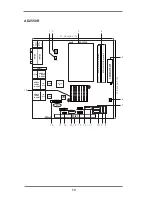
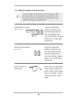
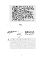
Speaker Header
(4-pin SPEAKER1)
(see p.10,12,14
)
B. Internet status indicator (2-pin LAN1_LED, LAN2_LED)
These two 2-pin headers allow you to use the Gigabit internet
indicator cable to connect to the LAN status indicator. When this
indicator flickers, it means that the internet is properly connected.
C. Chassis intrusion pin (4-pin CHASSIS)
This header is provided for host computer chassis with chassis
intrusion detection designs. In addition, it must also work with
external detection equipment, such as a chassis intrusion
detection sensor or a microswitch. When this function is activated,
if any chassis component movement occurs, the sensor will
immediately detect it and send a signal to this header, and the
system will then record this chassis intrusion event. The default
setting is set to the CASEOPEN and GND pin; this function is off.
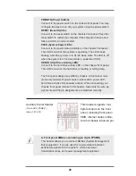
D. Locator LED (6-pin LOCATOR)
This header is for the locator switch and LED on the front panel.
Please connect the speaker
to this header.
1. High Definition Audio supports Jack Sensing, but the panel wire on
the chassis must support HDA to function correctly. Please follow the
instruction in our manual and chassis manual to install your system.
2. If you use AC’97 audio panel, please install it to the front panel audio
header as below:
A. Connect Mic_IN (MIC) to MIC2_L.
B. Connect Audio_R (RIN) to OUT2_R and Audio_L (LIN) to OUT2_L.
C. Connect Ground (GND) to Ground (GND).
D. MIC_RET and OUT_RET are for HD audio panel only. You don’t
need to connect them for AC’97 audio panel.
Front Panel Audio Header
This is an interface for front
(9-pin HD_AUDIO1)
panel audio cable that allows
(see
p.10)
convenient connection and
control of audio devices.

