background image

ASI Dental Specialties 

8 – SERVICING & PREVENTATIVE MAINTENANCE 


www.asisupport.com 

Page 4 

65-0059 Rev-C (04/27/21) 

OPTIONAL SUCTION INSTRUMENTS AND ACCESSORIES 

Daily 

1-Year  5-Years 

Inspect solids trap lid O-ring for wear. Lubricate using silicone O-ring grease (95-0085). Replace solids 

trap lid (PN 95-00091L) if needed. 


Inspect solids trap housing for cracks. Replace, if needed 


PN 95-0247 [Side Port] 


PN 95-0175 [Bottom Port] 


Inspect all suction tubing for leaks or damage. Replace, if needed. 


PN 95-0287 [HVE] 


PN 95-0288 [Saliva Ejector] 


Replace suction lever O-rings (PN 95-0040) and connector barb O-rings (PN 95-4034). 


STRUCTURAL 

Daily 

1-Year  5-Years 

Verify all doors, drawer hinges and latches are undamaged. Tighten fittings and lubricate, if needed. 


Cart Systems: Clean wheels and casters of all debris. 


FOR UMBILICAL UNITS ONLY 

Daily 

1-Year  5-Years 

Verify air pressure from main air connection is 75-80 psi; adjust if needed. ASI units risk damage if air 

pressure is set too high and will void the warranty 


FOR SELF-CONTAINED UNITS ONLY - VACUUM PUMP SYSTEM 

Daily 

1-Year  5-Years 

Empty sediment bowl per suction canister maintenance. 


Replace hose assembly/waste purge, peristaltic every 5 years: 


PN 95-0205 [Side Drain] 


PN 95-0334 [Bottom Drain] 


Inspect all vacuum tubing and fittings for leaks or damage. Replace, if needed. 


Replace felt filter muffler (PN 95-0093). 


Install rebuild kit for vacuum pump every 5-10 years, if needed. Serial Number specific: 


PN 95-0068 [SN 180319 and earlier] 


PN 95-0378 [SN 180320 and later] 


Test for proper function of purge pump and motor. Replace purge pump and motor (PN 95-0293), if 

necessary, every 5 years. 


Inspect exterior waste purge hose assembly. If worn, brittle, or hardened, replace every 5 years. Serial 

Number specific: 


PN 95-0306 [SN 200101 and earlier] 


PN 95-0401 [SN 200201 and later] 


FOR SELF-CONTAINED UNITS ONLY - INTERNAL AIR COMPRESSOR SYSTEM 

Daily 

1-Year  5-Years 

Inspect master air regulator for air leaks, proper function. Replace every 5 years, if needed. Serial 

Number specific: 


Upgrade to PN 95-0345 [SN 170100 and earlier] 


PN 95-0178A [SN 170101 and later] 


Inspect filter regulator setting and make sure it reads 75-80 psi, adjust, if needed 


Inspect tubing and replace, if needed. 


Inspect purge filter tubing and housing, replace if needed.  


Clean/rinse filter screen after daily purge 


Replace filter screen 


Replace felt filter muffler (PN 95-0093). 


Install rebuild kit for compressor every 5-10 years, if needed. Serial Number specific: 


PN 95-0069 [SN 180319 and earlier]  


PN 95-0378 [SN 180320 and later] 


Inspect and clean check valve. Replace, if needed (PN 95-0108). 


Test Compressor pressure switch for proper function. Replace, if needed (PN 95-0264). 


Содержание 90-2115

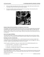
Страница 1: ...Models 90 2115 90 2125 This guide provides important steps for setup use and maintenance of the ASI delivery system It includes important details which must be followed to ensure safety and proper us...

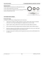
Страница 2: ...PRODUCT DESCRIPTION SPECIFICATIONS WARRANTY Intended Use Product Description Theory of Operation Dimensions Specifications Technical Data Warranty Information 4 UNPACKING INSTALLATION 5 START UP OPERA...

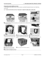
Страница 3: ...Section 1 Contents Symbols Safety Precautions www asisupport com 65 0047 Rev A 11 12 20 SYMBOLS DESCRIPTION OF DANGER LEVELS GENERAL SAFETY PRECAUTIONS IDENTIFICATION OF SYMBOLS 65 OS01 Rev A 11 12 20...

Страница 4: ...pressure before attaching or removing air lines or accessories or servicing this unit All air lines should be periodically inspected and replaced if worn or damaged If an outside compressed air suppl...

Страница 5: ...ly with applicable regulation regarding EMC and shall be installed and put into service according to the EMC information stated below WARNING Use of portable phones or other portable or mobile radio f...

Страница 6: ...ith UL 61010 1 2601 1 and under mutual recognition agreement with CAN CSA C22 2 No 601 1 Protective earth ground Functional earth ground Attention consult accompanying documents No user serviceable pa...

Страница 7: ...n 2 Contents Operating Environment Classification of Equipment www asisupport com 65 0048 Rev B 04 01 21 CLASSIFICATION OF EQUIPMENT EN 60601 1 ENVIRONMENTAL SPECIFICATIONS ELECTROMAGNETIC COMPATIBILI...

Страница 8: ...g where the intensity of electromagnetic disturbances is high ELECTROMAGNETIC COMPATIBILITY EMC Although this dental equipment conforms to the intent of the 2004 108 EC EMC Directive all medical equip...

Страница 9: ...pecified in this manual or referenced documents may result in increased electromagnetic emissions from this equipment or decreased electromagnetic immunity of this equipment Guidance and Manufacturer...

Страница 10: ...or hospital environment Surge EN IEC 61000 4 5 1kV differential mode line line 2kV common mode line earth 1kV differential mode line line 2kV common mode line earth Mains power quality should be that...

Страница 11: ...RF transmitters as determined by an electromagnetic site survey a should be less than the compliance level in each frequency range b Interference may occur in the vicinity of equipment marked with the...

Страница 12: ...pment Rated maximum output power of transmitter in watts W Separation distance according to frequency of transmitter in meters m 150kHz to 80MHz d 1 2 P 80MHz to 800MHz d 1 2 P 800MHz to 2 5GHz d 2 3...

Страница 13: ...T DENTAL DELIVERY SYSTEMS PRODUCT DESCRIPTION MODELS AVAILABLE THEORY OF OPERATION OVERVIEW OF COMPONENTS AND HOW THEY WORK Handpiece Control and Operation Tandem Water Disinfection System Air Compres...

Страница 14: ...and accessories Use of the system is intended only to support dental treatment and hygiene procedures and operation of dental instruments by or under the supervision of a licensed dentist All model co...

Страница 15: ...CATIONS AND WARRANTY www asisupport com Page 2 65 0104 Rev A 04 01 21 OVERVIEW OF COMPONENTS AND HOW THEY WORK Handpiece Control and Operation Tandem Water System Compressed Air System o Air Compresso...

Страница 16: ...nt and side of the unit Electric instruments such as the ultrasonic handpiece and electric motor are controlled via the same control block However the compressed air that flows from the block is route...

Страница 17: ...y increases the volume of water available but also saves costs by only requiring the use of one water line cartridge The system works by allowing water in the second bottle to flow into the first wher...

Страница 18: ...ces that enable a smooth running and quiet design The portable dental air compressor is controlled by an air pressure switch that senses when the pressure drops in the air tank to activate the motor a...

Страница 19: ...t the end of the day The system separates the air stream from the liquid and provides a sediment bowl that can be removed Built into the top of the holding tank is a float switch to prevent over filli...

Страница 20: ...ork done without first obtaining consent from ASI Specific Warranty Modifications The following items and or occurrences are not covered under the warranty Accidental Damage Theft including but not li...

Страница 21: ...I s supplemental warranty does not extend the original term of the manufacturer s warranty does not include items not covered under the manufacturer s warranty or warranty problems caused by or result...

Страница 22: ......

Страница 23: ......

Страница 24: ......

Страница 25: ......

Страница 26: ......

Страница 27: ......

Страница 28: ......

Страница 29: ......

Страница 30: ......

Страница 31: ......

Страница 32: ......

Страница 33: ...Section 4 Contents Unpacking and Installation www asisupport com 65 0114 Rev A 02 08 21 UNPACKING ELECTRICAL INSTALLATION...

Страница 34: ...ed to a central air supply appropriate electrical supply and optional vacuum and water supply Connection of umbilical lines from the cart to an appropriate junction box are the responsibility of the u...

Страница 35: ...er Syringe Handpieces Fiber Optics HANDPIECE OPERATION Fiber Optics Operation Verify Handpiece Operation Handpieces Holders Coolant Operation Adjusting Coolant Spray Adjusting Chip Air Flow Oil Mist R...

Страница 36: ...tch for supplying air pressure to the bottles Flip the switch to the OFF position to turn off the air supply to the bottles Slowly unscrew the bottles to allow them to depressurize Clean as appropriat...

Страница 37: ...p assuring proper insertion and that the locking mechanism is engaged Handpieces Verify Handpiece Placements Ensure all handpieces are placed into their correct holders and that the corresponding tubi...

Страница 38: ...pray allows water to flow up to high speed handpieces and to be sprayed onto the bur 5 Blank Hole This hole is non operative but is intended to still allow the use of a fiber optic handpiece in the st...

Страница 39: ...Place the handpiece onto the coupler and ensure that the tubes from the handpiece align in the connector and that the gasket on the back of the handpiece is seated against the connector Then firmly ti...

Страница 40: ...other instruments Water can also be sprayed from instruments to ensure it is working correctly Handpieces Holders The handpieces are automatically activated for use with the foot control whenever the...

Страница 41: ...also be desired to shut down chip air flow for some treatment procedures In this case rotate the knob counter clockwise until it stops Oil Mist Recovery Jar Air from an air driven handpiece is exhaus...

Страница 42: ...never it is not in use The strength of the vacuum pull to the oral evacuation system is regulated by the vacuum relief valve The relief valve on the system is pre set to approximately 12 Hg which is i...

Страница 43: ...Exterior Cleaning and Worktop Worktops and Control Panel Overlays Painted Work Surfaces and Handpiece Holders Wiping Down Disinfecting Handpiece Tubings Disinfection of Clean Water System Handpiece St...

Страница 44: ...n the suction canister The canister holds up to 2 liters of solution When the canister is full an overflow shut off device will disable the vacuum pump until purged IMPORTANT Do not fill the canister...

Страница 45: ...n OFF the purge pump switch and rewind the purge hose 8 After the diluted solution is purged out from Step 2 above suction up 2 ounces of pure concentrated Keep Clear solution or place an atomizer cap...

Страница 46: ...dental unit utilizes a container to assist in capturing excess handpiece lubricant This Oil Mist Recovery Jar is located under the left side of the system behind the holder bar Exhaust lines of the pn...

Страница 47: ...eaning and Worktop The exterior of the delivery unit should be thoroughly cleaned and disinfected after use each day to maintain optimal performance All components should be maintained in proper worki...

Страница 48: ...rtridge will no longer provide disinfection for the system and may plug the unit and obstruct the water flow Do not use the DentaPure DP365 if using a shock treatment to disinfect lines as it will dam...

Страница 49: ...pieces 3 Remove the HVE or saliva ejector valve micro evacuator body from the tubing by pulling it away from the tubing to disconnect from the barb end that remains in the tubing 4 Remove the control...

Страница 50: ...Empty the water containers and purge handpiece coolant lines and the water syringe See Operation Instructions Run air through the handpieces for an additional three minutes to air dry 2 Purge the was...

Страница 51: ...nd tie to secure Remove the lid from the trunk and set the main part of the trunk on end Lift out the caster ramp and remove the foam insert from the top Carefully roll and push the cart into the trun...

Страница 52: ...ssure to the Handpiece Air or Water Coming out of Handpieces When Hung Up Water Filling Up Oil Mist Recovery Jar Water Not Flowing From Handpieces or Air Water Syringe Water Flows from Air Water Syrin...

Страница 53: ...at handpiece has been opened Ensure that the exhaust air tubes and oil mist recovery jar are allowing the air to exhaust freely Verify that there is no kinked exhaust tubing to the oil mist recovery j...

Страница 54: ...the control block and verify that the ridged side of the diaphragm puck is facing down Water Not Flowing From Handpieces or Air Water Syringe Check the water bottles and ensure they are full switched...

Страница 55: ...ation If water drips from several handpieces or if water slowly builds and drips out the water relay may not be working or has a small piece of debris in it Replace the water relay valve o Replace wit...

Страница 56: ...ing Grease Use only silicone lubricant when lubricating instrumentation O rings Petroleum products will cause permanent damage to the O rings If air is blowing out of foot control the diaphragm in the...

Страница 57: ...ervicing Preventative Maintenance www asisupport com 65 0059 Rev C 04 27 21 CUSTOMER SUPPORT REPLACEMENT PARTS List of Replacement Parts Kits for this System SERVICE PREVENTATIVE MAINTENANCE DAILY 1 Y...

Страница 58: ...115V PN 95 0416 Air Compressor Manifold DV PN 95 0417 Compressor and Vacuum Rebuild Kit PN 95 0378 Check Valve Repair Kit PN 95 0108 Vacuum Pump 115V PN 95 0167 Vacuum Pump DV PN 95 0167D Capacitor fo...

Страница 59: ...ERVICE Please follow the following steps for service of your equipment Start with Section 7 Troubleshooting This section is designed to help narrow down most common problems Visit ASIsupport com Tech...

Страница 60: ...oggle PN 95 0242 if needed X CLOSED WATER SYSTEM Daily 1 Year 5 Years Turn air pressure toggle to ON Verify closed water system gauge is operational Check for cracks or air leaks Replace gauge PN 95 0...

Страница 61: ...ct all vacuum tubing and fittings for leaks or damage Replace if needed X Replace felt filter muffler PN 95 0093 X Install rebuild kit for vacuum pump every 5 10 years if needed Serial Number specific...

Страница 62: ...inge Closed Water System Instrument Component Pan View Air Compressor Complete Assembly Diagram Air Tank Dual Bracketed Complete Assembly Vacuum Pump Complete Assembly Diagram Sediment Separator and H...

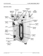
Страница 63: ...ASI Dental Specialties 9 BACK VIEW DIAGRAM TRITON www asisupport com Page 1 65 0062 Rev A 11 12 20 BACK VIEW TRITON 65 OS01 Rev A 11 12 20...

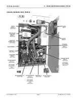
Страница 64: ...ASI Dental Specialties 9 CHASSIS INTERIOR DIAGRAM TRITON www asisupport com Page 1 65 0063 Rev A 11 12 20 CHASSIS INTERIOR VIEW TRITON...

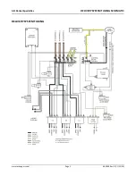
Страница 65: ...ASI Dental Specialties DELIVERY SYSTEM TUBING SCHEMATIC www asisupport com Page 1 65 0064 Rev A 11 12 20 DELIVERY SYSTEM TUBING 65 OS01 Rev A 11 12 20...

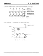
Страница 66: ...tal Specialties 9 CONTROL BLOCK DIAGRAM www asisupport com Page 1 65 0065 Rev B 02 08 21 5 POSITION CONTROL BLOCK FRONT OUTPUT CONNECTIONS TO HANDPIECE 5 POSITION SINGLE CONTROL BLOCK SIDE INPUT CONNE...

Страница 67: ...ASI Dental Specialties 9 FOOT CONTROL DIAGRAM www asisupport com Page 1 65 0069 Rev A 11 12 20 FOOT CONTROL 65 OS01 Rev A 11 12 20...

Страница 68: ...in Quick Clean Syringe Button 3a Air Only Syringe 3b Air Water Syringe 4 Tip Adapter Assembly 5 Large O Ring Tip Adapter 6 Spring Tip Adapter 7 O Ring Tip Adapter 8 Button Assembly 9 O Ring Button Ass...

Страница 69: ...ASI Dental Specialties 9 CLOSED WATER SYSTEM DIAGRAM www asisupport com Page 1 65 0071 Rev A 11 12 20 CLOSED WATER SYSTEM 65 OS01 Rev A 11 12 20...

Страница 70: ...le 1 PN95 0198 Power Supply Curing Light 1 Power Supply Kavo Motor 1 Controller Fiber Optic System 1 PN 95 0229 Power Controller Kavo Motor 1 Oil Mist Recovery Jar Handpiece Exhaust 1 PN 95 0258 Trans...

Страница 71: ...ASI Dental Specialties 9 AIR COMPRESSOR DIAGRAM www asisupport com Page 1 65 0073 Rev A 11 12 20 AIR COMPRESSOR ASSEMBLIES Single Voltage PN 95 0197 Dual Voltage PN 95 0159D 65 OS01 Rev A 11 12 20...

Страница 72: ...ASI Dental Specialties 9 AIR COMPRESSOR TANK ASSEMBLY DIAGRAM www asisupport com Page 1 65 0074 Rev A 11 12 20 AIR TANK ASSEMBLY 80 0192 65 OS01 Rev A 11 12 20...

Страница 73: ...ASI Dental Specialties 9 VACUUM PUMP ASSEMBLY DIAGRAM www asisupport com Page 1 65 0075 Rev A 11 12 20 VACUUM PUMP ASSEMBLIES Single Voltage PN 95 0167 Dual Voltage PN 95 0167D 65 OS01 Rev A 11 12 20...

Страница 74: ...ASI Dental Specialties 9 SEDIMENT SEPARATOR DIAGRAM www asisupport com Page 1 65 0076 Rev A 11 12 20 SEDIMENT SEPARATOR HOLDING TANK PN 95 0343 65 OS01 Rev A 11 12 20...

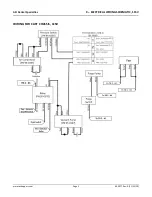
Страница 75: ...ASI Dental Specialties 9 ELECTRICAL WIRING SCHEMATIC 115V www asisupport com Page 1 65 0077 Rev A 11 12 20 WIRING FOR CART CHASSIS 115V 65 OS01 Rev A 11 12 20...

Страница 76: ...ASI Dental Specialties 9 ELECTRICAL WIRING SCHEMATIC 115V www asisupport com Page 2 65 0077 Rev A 11 12 20 WIRING FOR CART BASEPLATE 115V 65 OS01 Rev A 11 12 20...

Страница 77: ...ASI Dental Specialties 9 PURGE PUMP ASSEMBLY DIAGRAM 115V www asisupport com Page 1 65 0078 Rev A 11 12 20 PURGE PUMP ASSEMBLY 115V PN 95 0404 65 OS01 Rev A 11 12 20...

Страница 78: ...ASI Dental Specialties 9 PRESSURE SWITCH DIAGRAM 115V www asisupport com Page 1 65 0079 Rev A 11 12 20 PRESSURE SWITCH 115V 65 OS01 Rev A 11 12 20...

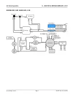
Страница 79: ...ASI Dental Specialties 9 ELECTRICAL WIRING SCHEMATIC DV www asisupport com Page 1 65 0080 Rev A 11 12 20 WIRING FOR DUAL VOLTAGE CHASSIS 65 OS01 Rev A 11 12 20...

Страница 80: ...ASI Dental Specialties 9 ELECTRICAL WIRING SCHEMATIC DV www asisupport com Page 2 65 0080 Rev A 11 12 20 WIRING FOR DUAL VOLTAGE BASEPLATE 65 OS01 Rev A 11 12 20...

Страница 81: ...ASI Dental Specialties 9 PURGE PUMP ASSEMBLY DIAGRAM DV www asisupport com Page 1 65 0081 Rev A 11 12 20 PURGE PUMP ASSEMBLY PN 95 0293 65 OS01 Rev A 11 12 20...

Страница 82: ...ASI Dental Specialties 9 PRESSURE SWITCH ASSEMBLY DIAGRAM DV www asisupport com Page 1 65 0083 Rev A 11 12 20 PRESSURE SWITCH ASSEMBLY DUAL VOLTAGE 65 OS01 Rev A 11 12 20...

Отзывы: