Operation
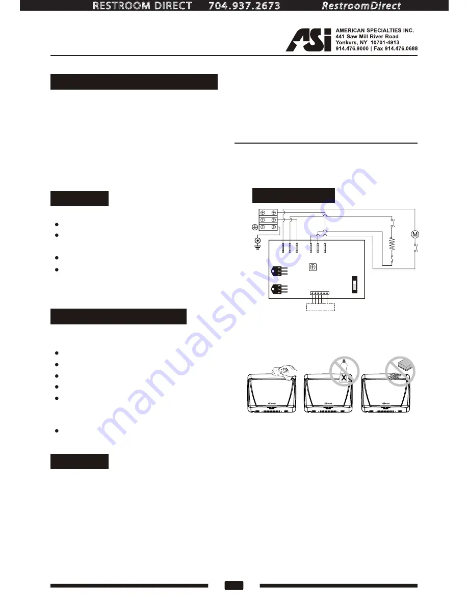
Periodic cleaning of the unit is recommended to ensure optimum performance.
Disconnect the electrical supply.
Remove the two cover-mounting screws.
Remove the cover.
Clean all dust lint from the interior of the dryer.
Replace the cover. Do not over tighten the screws.
Wipe the cover with a damp cloth and mild
cleaning solution. Do not Soak. Never use
abrasives to clean the cover.
Cleaning and Maintenance
50"
3
www.americanspecialties.com
Warranty
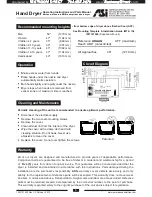
Recommended mounting heights
-
from bottom edge of dryer above finished floor (AFF)
See Mounting Template & Installation Guide (MT & IG)
1207101509
(Supplied with unit)
Men
Women
Children 4-7 years
Children 8-10 years
Children 11-13 years
Children 14-16 years
Handicaped
(1270 mm)
47"
(1194 mm)
35"
(889 mm)
39"
(991 mm)
43"
(1092 mm)
47"
(1194 mm)
40"
(1016 mm)
All Approaches
48"
(1219 mm)
Reference
ADAAG
Reach LIMIT (unrestricted)
AFF (maximum)
All of our dryers are designed and manufactured to provide years of dependable performance.
Component parts are guaranteed to be free of defects in material and workmanship for a period
of
Five (5)
years from date of original invoice. This guarantee will be honored provided that the
dryer is installed and maintained in accordance with the instructions. Parts damaged during the
installation are the purchaser's responsibility.
ASI's
warranty covers defects exclusively, and only
liability for the replacement of defective parts will be accepted. This warranty does not cover wear
and tear, or misuse and abuse. Transportation, freight costs and labor are also excluded. Defective
parts must be returned prepaid, accompanied by the unit serial number, to the point of purchase.
This warranty is granted solely to the original purchaser of the unit and is subject to registration.
Circuit Diagram
S
hake excess water from hands.
P
lace hands under the nozzle and dryer
automatically starts operation.
R
ub hands lightly and rapidly under the nozzle.
D
ryer stops when hands are removed from
sensor zone or if maximum time is reached.
Patented
Operating Instructions and Parts Manual
Hand Dryer
Surface-mounted
ADA
-compliant hand dr yer
Circuit Board Module
0199-1/ 0134-1 P/N A0255
0199-2/ 0134-2 P/N A0256
0199-3/ 0134-3 P/N A0257
Transistor
Power Switch
MO2 HE2
N
MO1 HE1
L
Transistor
Power Switch
VR
G
N
L
Thermostat
Red (110-120~Vac)
(208-240~ 277~Vac)
/
Blue
Black
Black
G/Y
B
lu
e
B
ro
w
n
P/N A0259
M
o
to
r
W
it
h
T
h
e
r
m
a
l
S
w
it
c
h
2
A
0
1
9
9
-1
/
0
1
3
4
-1
P
/N
0
1
9
9
-2
/
0
1
3
4
-2
,
0
1
9
9
-3
/
0
1
3
4
-3
P
/N
A
0
2
4
7
A
0
2
4
8
Hea
ter
W
ith
T
her
mo-fuse
0199-1/ 0134-1
P/N
0199-2/ 0134-2, 0199-3/ 0134-3
P/N
A0249
A0250
FOR MOTOR
SW.
FOR HEATER
White (110-120~Vac)
(208-240~ 277~Vac)
/
Brown
Sensor module
ON
1
1207131423 Rev C 3 October. 2013
distributed by
RESTROOM DIRECT 704 . 937. 2673
www.
RestroomDirect
.com

