background image

-12

-

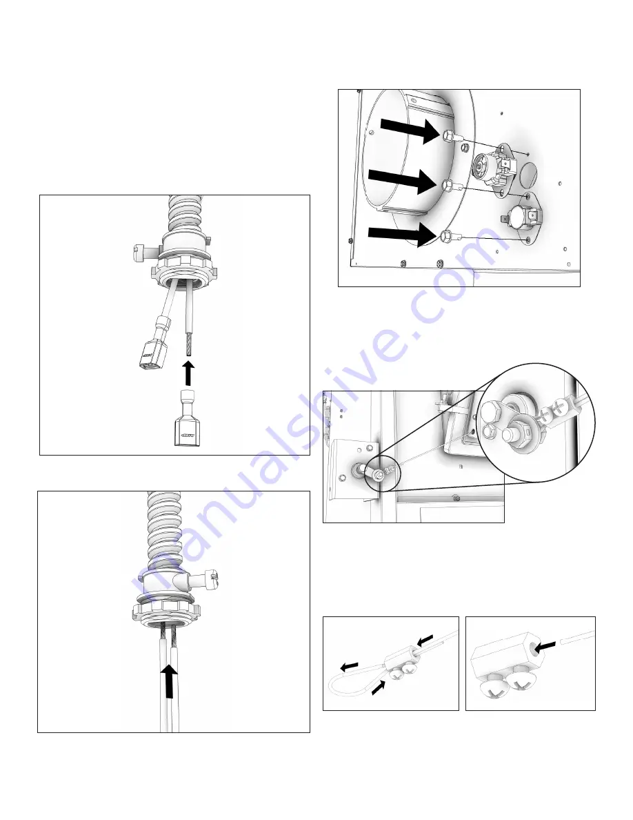
ÉTAPE 7

Rattachez le 

couvercle à 

l’aide des 

quatre vis 

# 10 

X 1/2 

retirées précédemment.

ÉTAPE 8

Insérez le 

fi  l dans 

le serre-câble 

et faites 

une boucle 

comme 

indiqué, puis retournez le fi  l dans le serre-câble.

ÉTAPE 9

Connectez le 

fi  l au 

bras de 

servo en 

faisant passer 

le fi l 

autour 

du boulon 

1 / 

4-20 X 

3/4 comme 

indiqué. Une 

fois la 

boucle 

en place, 

réduisez la 

taille de 

la boucle 

pour la 

rendre plus 

petite que 

la rondelle. 

Cela l’empêchera 

de glisser 

une fois 

que l’unité 

est en 

marche. Serrez 

les deux 

vis afi

 n 

que le 

fi  l ne 

puisse pas bouger.

ÉTAPE 10

Fixez le 

fi  n 

de course 

non réglable 

et le 

thermodisque réglable 

à l’arrière 

de l’appareil, 

comme indiqué 

en utilisant 

(3) trois 

vis n 

° 10 

X 1/2. 

REMARQUE: L’interrupteur 

de fi n 

de course 

non rég

lable doit 

être install

é au-dessus 

du thermodisque 

réglable.

ÉTAPE 11

Faites passer 

les deux 

fi  ls 

rouges fournis 

avec ce 

kit dans 

le 

conduit existant 

qui va 

de la 

boîte de 

jonction jusqu’à 

la 

boîte de montage du support T’stat.

ETAPE 12

Fixez les bornes femelles aux deux extrémités des fi  ls rouges.

ETAPE 13

Connectez le 

conduit au 

thermodisque (voir 

«Schéma 

de câblage 

de l’amortisseur 

thermostatique» pour 

une 

installation correcte 

du câblage). 

Rattachez l’assemblage 

du support 

T’stat à 

l’arrière de 

l’unité à 

l’aide de 

(4) quatre 

vis n ° 10 X 1/2.

Содержание AF1500E

Страница 1: ...ng or fire officials about permits restrictions and installation requirements in your area CAUTION Please read this entire manual before you install or use this unit Failure to follow instructions may...

Страница 2: ...furnace main disconnect Respect all local and national codes when installing this unit This unit is not to be connected to a chimney ue serving another appliance This unit is designed to burn solid h...

Страница 3: ...t not be altered It is against federal regulations to alter this setting or otherwise operate this wood heater in a manner inconsistent with operating instructions in this manual The operation of this...

Страница 4: ...re Do not leave the furnace unattended when the door is slightly opened Do not burn garbage ammable uid such as gasoline naphtha or motor oil Always close the door after the ignition Consult your muni...

Страница 5: ...See kit installation section in this manual to ensure proper assembly installation and operation of your new furnace If installing in an area with a fan it should not be allowed to create negative pre...

Страница 6: ...doing the installation yourself before you decide which installation will best suit your needs consult a qualified heating technician and follow his recommendations as to the safest and most efficient...

Страница 7: ...ly from the junction box to the thermostat bracket Crimp the two female terminals to each of the wire leads Plug the wires to the thermodisc NOTE It does not matter which of the two wires plugs to whi...

Страница 8: ...rtain in place above the fuel feed door as shown After installation the smoke curtain should swing freely back into the furnace DOOR LATCH INSTALLATION Use the two included bolts and nuts to secure th...

Страница 9: ...ian It is recommended to connect the furnace to its own 15 amp 120 Volt circuit from the house power supply 105 C NOTE Wire leads from the distribution blower are usually BOTH BLACK Makes no differenc...

Страница 10: ...uator will need to be mounted ush against the stove Insure the actuator is mounted ush by removing the panel screw before mounting the actuator STEP 5 Take off the cover by removing 4 four 10 X 1 2 sc...

Страница 11: ...the wire is not able to move STEP 10 Attach the non adjustable limit switch and adjustable thermodisc to the back of the unit as shown using 3 three 10 X 1 2 screws NOTE The non adjustable limit switc...

Страница 12: ...using 2 two 10 X 1 2 screws STEP 16 Complete all wiring see Thermostatically Controlled Damper Wiring Diagram for proper wiring installation Once the wiring is completed attach the fan center transfor...

Страница 13: ...WHITE WHITE BLACK BLACK BLACK RED RED RED BLACK BLUE BLUE BLACK BLACK BLACK GREEN GROUND 120 VAC 60 HZ 15 AMPS NOTE WIRES FROM DISTRIBUTION FAN RUN DIRECTLEY INTO THE 4 X 4 JUNCTION BOX WHITE WHITE WH...

Страница 14: ...askets to the furnace if not already mounted 3 If your BX Cables will not match up to the previously matched arrangement on the top carefully measure and custom notch to accommodate your particular ar...

Страница 15: ...at is being cooled by the ambient air outside the house Therefore the gas which circulates will cool slower thus reducing the build up of creosote and the risk of chimney fires The draft caused by the...

Страница 16: ...ector and a minimum 24 gauge ventilated wall thimble which has two air channels of 1 25 4 mm each construct a wall pass through There shall be a minimum 6 152 4 mm separation area containing fiberglas...

Страница 17: ...re a good draft the total length of the furnace pipe should never exceed 8 to 10 2 4m to 3 04 m Except for cases of vertical installation cathedral roof style where the smoke exhaust system can be muc...

Страница 18: ...imum amount of combustion air during the initial start up to insure the fastest and cleanest start up The primary air will be in the High position when the thermostat is calling for heat These setting...

Страница 19: ...the stove reacts You can increase the number of logs burned at a time to making sure the temperature never rises higher than 475 F 246 C on a magnetic thermometer for installation on single wall stov...

Страница 20: ...of the piece your wood is soaked or freshly cut Do not use this wood in your furnace Large amounts of creosote could be deposited in your chimney creating potential conditions for a chimney fire THE F...

Страница 21: ...ine with expelled moisture to form creosote The creosote vapors condense in the relatively cool chimney ue of a slow burning fire As a result creosote residue accumulates on the ue lining When ignited...

Страница 22: ...HV of the fuel The lower heating value is when water leaves the combustion process as a vapor in the case of wood stoves the moisture in the wood being burned leaves the stove as a vapor The higher he...

Страница 23: ...hange the door gasket which makes your furnace door air tight once a year in order to insure good control over the combustion maximum efficiency and security To change the door gasket simply remove th...

Страница 24: ...cement Parts Wooden Knob Assembly 892767 3 Gasket Flue Collar 88032 1 Ring Flue Collar 22761 1 Flue Collar 6 C I 40246 1 Stub Collar 8 891214 2 Handle Assembly 891098 1 Ashpan Weldment 610498 1 Assemb...

Страница 25: ...l Mounting Bracket 22140 1 T Disc 200 20 F 80789 1 Actuator Conduit Assy 610850 1 Cabinet Back 27883 1 Cabinet Top 25562 1 Hinge Spacer 24232 1 Tertiary Damper Shield 27909 1 Left Cabinet Side 25467 1...

Страница 26: ...Replacement Parts Wooden Handle 89520 1 Board Ceraminc Fiber 892726 2 Secondary Tube 86870 6 Brick Retainer 27879 2 Slide Plate Assembly 610750 1 Right Shoulder 28015 1 Blower Assembly 80594 2 Back P...

Страница 27: ...e warranty Replacement Parts Left Heat Shield 28789 1 76 76 ROOM TEMP SET TEMP SYSTEM HEAT F F Filter Box Medium Panel 28708 2 Right Heat Shield 28790 1 Right Cabinet Side 28665 1 Servo Bracket 28613...

Страница 28: ...07 Date _____________________ Engineer Name ________________________________ License No ____________________________________ Company _____________________________________ Telephone No _______________...

Страница 29: ...29 Notes...

Страница 30: ...Notes...

Страница 31: ...de rechange Conservez ce manuel dans un endroit s curitaire pour une consultation ult rieure cette fin assurez vous de toujours fournir le num ro de mod le se trouvant sur la fiche signal tique attac...

Страница 32: ..._______ Service 07 Date ____________________ Nom de l ing nieur ____________________________ No de licence _________________________________ Entreprise _____________________________________ N de t l p...

Страница 33: ...7924L 2 Disque thermique 60 C 140 F ajustable 80388 1 C ble en acier galvanis 892951 1 Thermostat num rique mural 80779 1 Afin de conserver la garantie les composants doivent tre remplac s l aide des...

Страница 34: ...tanch it du ventilateur 89319 2 Assemblage soud du couvercle 610752 1 Transformateur centre du ventilateur 80130 1 paulement gauche 28016 1 Guide fil 28746 1 Serre c ble 83785 1 Afin de conserver la g...

Страница 35: ...de verrouillage porte d alimentation 891097 1 Assemblage de la porte d alimentation 68217 1 cran du registre secondaire 27908 1 Charni re de porte de la porte d alimentation 22662 1 Assemblage du reg...

Страница 36: ...6 po 40246 1 Bague d extr mit C I 203 mm 8 po 891214 2 Assemblage de la poign e en bois 892767 3 Assemblage de poign e de porte 891098 1 Assemblage soud du bac cendre 610498 1 Assemblage porte d limi...

Страница 37: ...int d tanch it d un diam tre de 13 mm 1 2 po PEINTURE Nettoyez uniquement votre fournaise avec un chiffon doux qui n endommagera pas le fini de la peinture Si la peinture est gratign e ou endommag e i...

Страница 38: ...CTEURS DE FUM E ET DE CO Le br lage du bois produit naturellement des missions de fum e et du monoxyde de carbone CO Le CO est un gaz poison lorsque l exposition se fait des concentrations lev es pour...

Страница 39: ...es temp ratures plus basses Au del de 260 500 degr s la chaleur est gaspill e par une trop grande quantit de chaleur perdue dans l atmosph re POUR VITER L ACCUMULATION DE CR OSOTE Br lez toujours du b...

Страница 40: ...oit durcir pour en pr server sa qualit Une fois le combustible correctement allum ne br lez que des petits feux pendant les premi res heures de fonctionnement N ouvrez jamais la commande d air plus qu...

Страница 41: ...iqu e et voyez la r action du po le Vous pouvez augmenter le nombre de b ches br l es la fois en vous assurant que la temp rature ne s l ve jamais au del de 246 C 475 F sur un thermom tre magn tique i...

Страница 42: ...aire sera en position lev e lorsque le thermostat effectue un appel de chaleur Ces r glages doivent demeurer ouverts jusqu ce que le po le se r chauffe et qu un feu ad quat s est tabli Une fois le feu...

Страница 43: ...3 04 m 8 10 pi Sauf dans les cas d une installation verticale o le syst me d vacuation de la fum e d un toit de style cath dral peut tre beaucoup plus long et se brancher sans probl me la chemin e du...

Страница 44: ...r fabriqu e homologu e d au moins 304 mm 12 po avec un isolant de 25 4 mm 1 po ou plus et au diam tre interne de 203 mm 8 po 51 mm 2 po plus grand que le conduit de raccordement de 152 4 mm 6 po Utili...

Страница 45: ...de chemin e Le tirage caus par la tendance l air chaud de s lever sera augment par une chemin e int rieure Utiliser un pare feu l extr mit de la chemin e exige une inspection r guli re pour assurer qu...

Страница 46: ...urs et les joints d tanch it la fournaise si elle n est pas d j mont e 3 Si vos c bles BX ne s agencent pas l arrangement pr c dent du haut mesurez soigneusement et pratiquez une encoche pour accommod...

Страница 47: ...LEU NOIR NOIR NOIR VERT MISE LA TERRE 120 V c a 15 A DU VENTILATEUR DE DISTRIBUTION PASSENT DIRECTEMENT DANS LA BO TE DE JONCTION 4X4 BLANC BLANC BLANC NOIR NOIR NOIR NOIR BLANC VENTILATEUR DE DISTRIB...

Страница 48: ...vis 10 X 1 2 TAPE 16 Terminez tout le c blage consultez la section Sch ma de c blage de l amortisseur thermostatique pour une installation correcte du c blage Une fois le c blage termin fi xez le tra...

Страница 49: ...bouger TAPE 10 Fixez le fi n de course non r glable et le thermodisque r glable l arri re de l appareil comme indiqu en utilisant 3 trois vis n 10 X 1 2 REMARQUE L interrupteur de fi n de course non...

Страница 50: ...24 X 1 2 dans les trous pr perc s situ s sur le c t sup rieur droit de l appareil REMARQUE L actionneur devra tre mont plat contre le po le Assurez vous que l actionneur est mont plat en retirant la...

Страница 51: ...TEUR ALIMENTATION LECTRIQUE MISE LA TERRE MOTEUR DU VENTILATEUR NOIR NOIR BLANC BLANC COMMANDE DU VENTILATEUR ALIMENTATION LECTRIQUE Disque thermique Mise la terre Bo te de jonction lectrique MOTEUR D...

Страница 52: ...te d alimentation en combustible comme il est indiqu Apr s l installation l cran de cantonnement doit de balancer librement vers la fournaise INSTALLATION DU VERROU DE PORTE Utilisez les deux boulons...

Страница 53: ...emelles chacun des fils conducteurs Branchez les fils au disque thermique REMARQUE Il n a aucune importance quelle borne du disque thermique est branch un fil 3 Retirez les ventilateurs de leur bo te...

Страница 54: ...imale de 610 mm 24 po si le haut de la premi re section verticale n est pas galit avec le haut de la premi re section horizontale du r seau de gaines Si le haut de la chambre de r partition est galit...

Страница 55: ...DE PLANCHER PROTECTEUR DE PLANCHER La fournaise doit tre plac e sur du b ton plein de la ma onnerie pleine ou si install sur un plancher in ammable sur un protecteur de plancher Le protecteur de plan...

Страница 56: ...ns le pr sent manuel afin de proc der l assemblage appropri l installation et le fonctionnement de votre nouvelle fournaise Si l installation se fait dans un endroit avec un ventilateur il ne devrait...

Страница 57: ...as utiliser de produits chimiques ou de uides pour allumer le feu Ne pas laisser la fournaise sans attention lorsque la porte est l g rement ouverte Ne br lez pas de d chets de liquide in ammable tel...

Страница 58: ...lisation autre de ce chauffage au bois qui ne respecterait pas les directives du pr sent manuel contrevient aux r glementations f d rales Utiliser ce chauffage au bois en ne respectant pas le manuel c...

Страница 59: ...spectez tous les codes locaux et nationaux lors de l installation de cette unit Cette unit ne doit pas tre branch e une chemin e servant pour un autre appareil Cette unit n est con ue que pour br ler...

Страница 60: ...METTANT DE CORRECTEMENT COMMANDER LES PI CES DE RECHANGE GARDEZ DANS UN ENDROIT S CURITAIRE POUR UNE CONSULTATION ULT RIEURE AVIS DE S CURIT Si cette unit n est pas correctement install e un incendie...

Отзывы: