


Page 1
GENERAL SERVICE INFORMATION
This service and parts manual offers technicians informa-
tion and parts lists not available in the AEU-7000L-70V or
AEU-7000E-70V Operation and Maintenance Instruction
Manuals. This manual will help you better understand
how the dental units work, thereby reducing service time.
Parts are listed and referenced to callouts in the Parts
Lists, pages 24 & 26. Use the information in the Parts List
when ordering replacement parts.
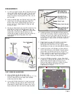
Inspection & Operation Verification
To verify that the 7000L/E units are set up and functioning
properly, refer to the set up instructions below and in their
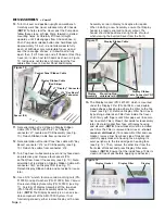
respective Operation & Maintenance manuals. First, attach
the power cord to the back of the console and plug into a
grounded electrical outlet (see Fig. 1).
NOTE:
Both 7000
series units are compatible with 115VAC, 60Hz and
230VAC, 50Hz voltages and frequencies.
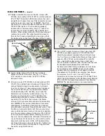
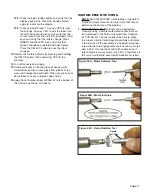
Connect the motor/cable to the receptacle on the lower
right front of the console
(see Fig. 2). When
attaching the cable to unit,
align the red dot on cable
connector with the arrows
located at top center of
receptacle and bezel, and
gently push the connector
straight in to lock into place.
Remove cord by pushing inward slightly on the strain relief,
then grasping connector body near the red dot and pulling the
connector straight out of receptacle.
Attach an ‘E’ Type 20:1 handpiece to the motor, and
install the Dynamometer Adapter into the handpiece (see
Fig. 3).
Attach the supplied AE-70V2 variable-speed foot control
to the connector located on the rear of the unit (see Fig.
1). The AE-23 Irrigation Tubing Set does not need to be
installed during routine maintenance and troubleshooting
of the console and/or motor. For troubleshooting irrigation
problems relative to the pump and/or irrigation tubing,
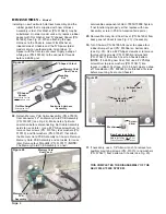
refer to System Troubleshooting on page 20. Turn the
power switch on the rear panel of the console to the ‘On’
(-) position. The vacuum fluorescent display should show
the startup screen for a few seconds, then default to the
operating parameters of the last-used preset (or preset #1
if the factory setup was recalled). The startup screen will
display the Aseptico logo and then the software version
onboard your 7000L/E unit (see Fig. 4)
.
Press the “RATIO” Up or Down buttons to select “20:1” on
the display (see Fig. 5). Depress the foot control pedal to
verify that the motor and pump operates. Press the “CAL”
button to calibrate the 7000L/7000E handpiece/motor.
Follow the menu prompts displayed on the screen to run the
handpiece through the two-part calibration procedure (
refer
to “OPERATION” section in the Operation Manual for
complete calibration instructions)
.
Press and hold the “SETUP” button for one second to enter
the AEU-7000L/7000E System Setup program (see Fig. 5).
Follow the menu prompts on the screen to recall the factory
setup, enable warning tones, and select other system
options (
refer to “OPERATION/System Setup” section in the
Operation Manual for complete setup instructions)
.
Verify that the “SPEED”, “TORQUE”, “FLOW”, “PRESETS”,
and key pad navigation buttons are functioning properly
(see Fig. 5). Press each button to verify that its displayed
values and/or LEDs change accordingly (
refer to
“CONTROL PANEL FUNCTIONS” section in the Operation
Manual for complete descriptions of all key pad buttons)
. On
the AEU-7000L unit only, press the Illumination Button (see
Fig. 5) and confirm that the LED on the handpiece
illuminates.
Figure 1
Power Cord
Connector
Foot Control
Connector
Fuses
Main Power
ON/OFF Switch
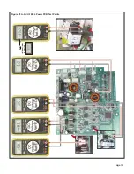
Figure 5
Figure 2
Alignment Arrows
Motor
Cable
Strain
Relief
E-TYPE
HANDPIECE
MOTOR
Figure 3
Calibration
Adapter
Figure 4
(Software
Version
Date)
(Software
Version)
RATIO Buttons
CAL
Button
SETUP Button
NAVIGATION Buttons
Motor
Cable
Connector
ILLUMINATION Button