


Page 8
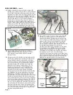
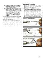
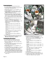
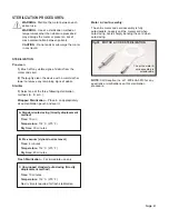
installing a new Footswitch Harness Assembly, and the
rubber gasket that is supplied with new Harness
Assembly is lost, Flat Washer [PN: 510648] may be
substituted. On older model units only, replace rubber
gasket with Flat Washer and 'D' shaped Spacer [PN:
461692]. See Fig. 23. When attaching the new
Harness to the Chassis, mount Flat Washer on
inboard side of Chassis and the 'D' Spacer [older
models only] on outboard side. Align tab on ‘D’
Spacer with the flat side of cutout.) Apply a drop of
white glue (PN: 490142) to the connector threads
before installing nut.
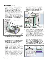
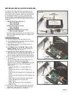
28.
Detach Memory PCB Cable Assembly (PN: 875078)
from connector 'J2" on Memory Card PCB Assembly
(PN: 330507) (see Fig. 24). Make note of pin/wire
orientation before disconnecting. Set Cable Assembly
aside for reuse later. Use a #2 Phillips screwdriver to
remove four screws (PN: 510746), lock washers (PN:
510010), and flat washers (PN: 510587) that attach
the Memory Card PCB Assembly to Chassis. Remove
Memory Card PCB Assembly and set aside for reuse
later. Remove four Standoffs (PN: 510747). (
NOTE:
The Memory Card PCB Assembly is a non-
serviceable component of AEU-7000L/7000E System.
If not functioning properly, either replace with new
Assembly or return PCB to Aseptico for repairs.)
29.
Remove Memory Card Dust Cover (PN: 461606) from
back panel of Chassis (see Fig. 23), if necessary.
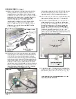
30.
Turn Chassis (PN: 461955-08) over to expose four
rubber Bumper Feet (PN: 850066) on bottom side
(see Fig. 25). Use a #2 Phillips screwdriver to remove
four mounting screws (PN: 510406) and washers
(PN: 510431) that attach Feet to Chassis bottom.
(
NOTE:
If installing new Feet, first use a #2 Phillips
screwdriver to press washers [PN: 510431] into
recess in rubber Feet [see Fig. 25 inset]. Apply a drop
of Threadlocker (PN: 490053) onto threads of screws
before mounting Feet onto Chassis.)
31.
If necessary, use a 1/8" Allen wrench to remove two
auxillary mounting screws (PN: 510312) and washers
(PN: 510421) from bottom of Chassis (see Fig. 25).
THIS COMPLETES THE DISASSEMBLY OF THE
AEU-7000L/7000E SYSTEM.
DISASSEMBLY -
Cont’d
Figure 25
Bumper Foot
(X4)
Auxillary Mtg.
Hardware
Before Installing New Foot,
Press Washer Into Recess
Washer
Screw-
driver
New Foot Installation
Figure 23
‘D’ Shaped
Spacer
Footswitch Harness
Assembly
Flat Washer
Mounting
Nut
(Substituted Part
on all models.)
(Substituted Part on
older models only.)
Memory Card
Dust Cover
‘D’ Shaped Cutout
Figure 24
Memory
PCB Cable
Assembly
Memory Card
Dust Cover
Connector
‘J2’
Memory Card
PCB
Assembly