4. The highlighted bracket on the front side of the bottom
case part should be broken off, as it will interfere with
the optional modules.
5. Solder two pieces of wire, about 15cm (6") long, to the
Cinch connector and its ground leads.
6. Put the connector's wires through the appropriate hole
in the back plate.
7. Attach the ground lead and solder the wires to the PCB.
8. Fasten the case with the included screws.
This completes the case mounting.
24
Содержание AE20401
Страница 23: ...Finished Component Side Finished Solder Side without the LCD LCD Mounting 17 ...
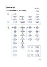
Страница 31: ...Operation Functions Menu Structure 25 ...
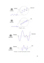
Страница 37: ...31 Example 1 noise Example 2 one signal superimposed on another ...
Страница 50: ...Circuit Diagram Part 1 2 44 ...
Страница 51: ...Part 2 2 45 ...
Страница 63: ... Nr of valid counts depends on range 57 ...
Страница 64: ...ASCEL ELECTRONIC www ascel electronic de 2015 ...


