Asahi/America SP-110S Скачать руководство пользователя страница 11


When the traceability data were entered, the machine displays the first input 
screen of the welding process proper (see 
Display 5). In this display, it is possible to 
start the welding process and to customize 
the configuration of the machine. 
 
The welder will enter all settings and perform 
all control actions on the touchscreen panel. 

4.3  Configuring the Machine 

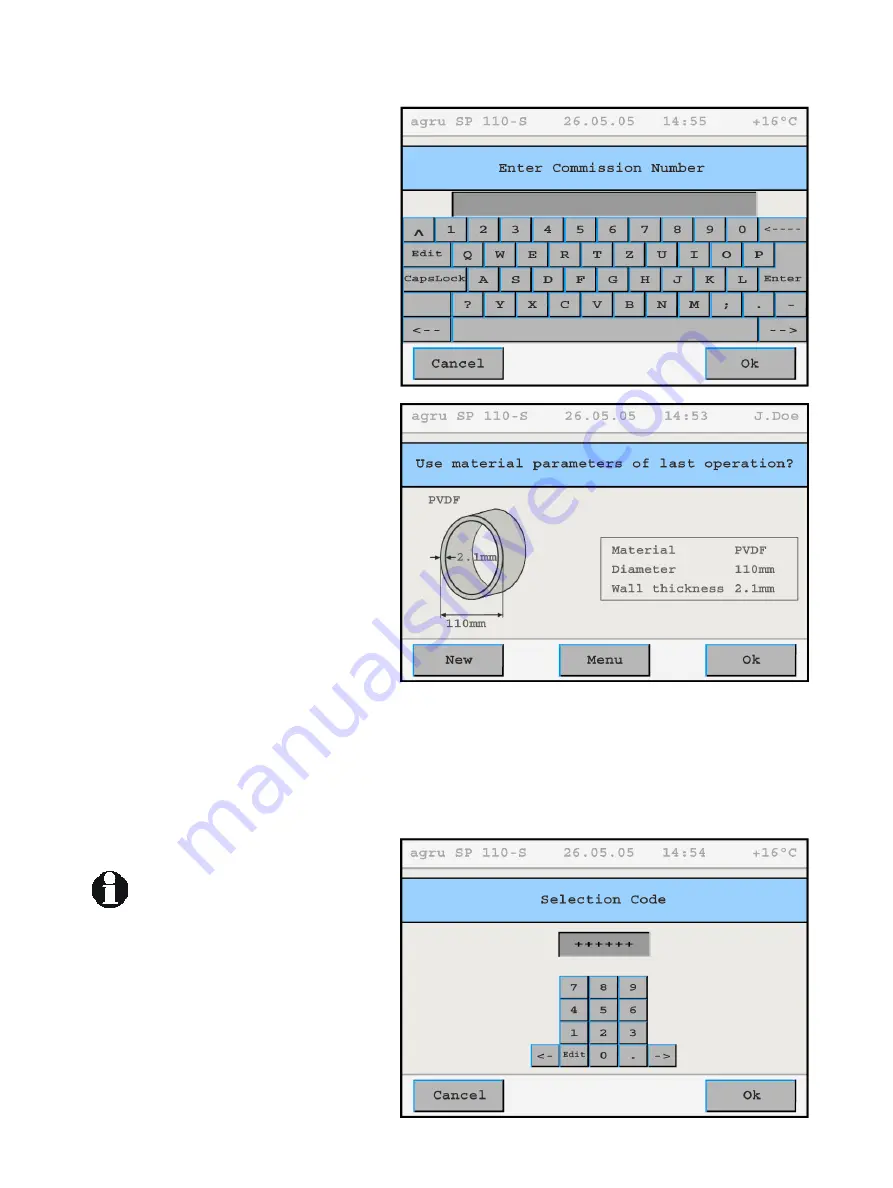
In the first input screen of the welding 
process proper (Display 5), the key data of 
the last welding are shown (material, diame-
ter, and wall thickness of the welded pipe). 
Furthermore, the status bar at the top of the 
screen shows the date, time of day, and also 
either the current ambient temperature or the 
power supply voltage or the welder’s name or 
code. 

Display 4

Info 

 
In Display 5, the welder has the possibility to: 

•  immediately start a welding process 


that will be performed with the same 
welding parameters as the previous 
welding (touch the “Ok” button and 
move on to section 4.6); 

•  enter new pipe-related data for the next 

welding (touch the “New” button and 
move on to section 4.4); 

•  change the machine settings in the con-

figuration menu (touch the “Menu” but-
ton); 

•  to read a new welder ID code using the 

scanning wand; or 

•  display the date for the next scheduled 

maintenance on the screen by touching 
“New” button for some time. 

Display 5

 
The first five options of the configuration menu are immediately accessible, 
the other options will be displayed only after an access code for the ma-
chine, the so-called selection code, was entered (see Display 6). The menu 
has the items listed in the following table. To toggle between various possi-
ble settings, or to open a sub-menu for a given menu item, touch the appro-
priate button. 

 
Some of the buttons next to menu 
option change their color when 
they were pressed and are then 
displayed as though the button is 
held down. In this case the “held 
down” button mean that this 
menu option is the selected 

ption. 

tains the options 

listed in the following table. 

o

 
The Configuration Menu con

Version December 2006 

agru SP 110-S User’s Manual 

11 

Display 6

Содержание SP-110S

Страница 1: ...ce Manual SP 110S 35 Green Street PO Box 653 Malden MA 02148 Tel 781 321 5409 Fax 781 321 4421 Toll Free 800 343 3618 www asahi america com asahi asahi america com Direct Sales East 800 232 7244 Centr...

Страница 2: ...ponents 7 3 2 Technical Specs 8 3 3 Welding Pipes and Fittings 9 4 Operation 9 4 1 Check out Turning on Selecting the display language 10 4 2 Entering traceability data for the joint 11 4 3 Configurin...

Страница 3: ...nual is applicable to the following machines agru SP 110S Thank you 2 Safety Messages This User s Manual contains important instructions for operating safely the infrared welding machine agru SP 110S...

Страница 4: ...m 30 feet from the circuit breaker Parts Under Power After opening the machine or removing the cover parts of it are accessible that may be under power The device may be opened exclusively by an autho...

Страница 5: ...are familiar with the applicable regulations the guidelines for the prevention of ac cidents and the User s Manual The machine may be operated only when observed Welders must have been introduced pro...

Страница 6: ...f the welding parameters contained in the control software is strictly prohibited It is also part of the intended use to conform to the instructions provided in the User s Manual The manufacturer can...

Страница 7: ...canning Wand Touchscreen Panel Set Screws for Compensation of Small Horizontal or Vertical Alignment Gaps Confirmation Button for Two Hand Mode Steps 3 2 2 Touchscreen Control Panel Status Bar Title B...

Страница 8: ...1 35 kW 0 24 kW Welding Operation Specs Welding Force Speed of Facing Tool Ambient Temperature operation Ambient Temperature storage Operating Range 10 500 N approx 45 rpm 0 C to 40 C 32 F to 104 F 5...

Страница 9: ...edefined force After the cooling time is over the force is automatically removed from the carriages and the pipe or fitting can be taken out of it 4 Operation 4 1 Check out Turning on Selecting the Di...

Страница 10: ...wand All inputs for which a bar code is available can be entered from the bar code using a scanning wand Entering data on the touchscreen must always be performed with the bare finger Using objects ba...

Страница 11: ...move on to section 4 6 enter new pipe related data for the next welding touch the New button and move on to section 4 4 change the machine settings in the con figuration menu touch the Menu but ton to...

Страница 12: ...red and the temperature of the heating mirror and the weld ing force can be zeroed calibrated Access to this sub menu requires an additional access code that is available from the manufacturer distrib...

Страница 13: ...nical welding parameters in the configuration menu Important W terial Therefore when this material is selected either from the default materials or from the additional materials if defined a message t...

Страница 14: ...described at the beginning of section 4 5 from the name of the pipe material through to the temperature the facing force Display 9 Touch the Edit Parameters button to change the value of a single wel...

Страница 15: ...o as to place the position handle into the rest that is labeled Pos 1 at the facing tool support Display 11 While the machine automatically performs a zeroing calibration of the carriage position when...

Страница 16: ...ent Ok button and to start the welding process the machine will tell you to move the car riage apart and to close the pipe butts at the far end from the heating ele ment with caps confirm this by Ok W...

Страница 17: ...ined by the key data for the welding operation previously entered or confirmed If a value is not within the applicable tolerance thresholds the machine shows an error message to this effect and the we...

Страница 18: ...ng and traceability data that will be saved to the report the screen resembles the one in Display 20 and asks the welder to remove the pipes and visually check the quality of the joint In case he find...

Страница 19: ...ange over or joining does not correspond to the expected distance it should travel welding has to be repeated Force Error The applied force is out of tolerance welding has to be repeated Power Supply...

Страница 20: ...he machine to the printer or the PC If you transfer the data to a PC make sure that the correct baud rate and interface type are set on the PC Depending on the printer used make sure Auto Carriage Ret...

Страница 21: ...en shows what is repro duced in Display 21 The time of day and the date can be set us ing the keypad shown on the touchscreen panel 6 2 Enabling Automatic Heating When the Automatic Heating sub menu w...

Страница 22: ...ng to be disabled first This can be done by touching either the Cancel button or the Enabled button which changes back to Disabled after this status change Important If automatic heating is neither ca...

Страница 23: ...sahi america com Equipment Rental Rental Equipment Manager 781 388 4618 toolmanager asahi america com Rental Administration Billing Returns 781 388 4623 toolrental asahi america com Field Technician O...

Страница 24: ...Street PO Box 653 Malden MA 02148 Tel 781 321 5409 Fax 781 321 4421 Toll Free 800 343 3618 www asahi america com asahi asahi america com Direct Sales East 800 232 7244 Central 800 442 7244 West 800 2...

Отзывы: