background image

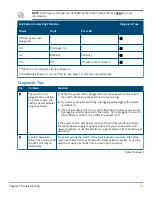
NOTE: Both Power and Fault are identified by the Global Status LED. See LEDs for more

information.

LED Pattern Indicating Problems

Diagnostic Tips

Power

Fault

Port LED

Off with power cord

plugged in

*

*

On

Prolonged On

*

On

Blinking†

Blinking†

On

Off

Off with cable connected

* This LED is not important for the diagnosis.

† The blinking behavior is an on/off cycle once every 1.6 seconds, approximately.

Diagnostic Tips

Tip

Problem

Solution

The switch is not

plugged into an active

AC power source, the

switch’s power adapter

may have failed.

1. Verify the power cord is plugged into an active power source and to

the switch. Make sure these connections are snug.

2. Try power cycling the switch by unplugging and plugging the power

cord back in.

3. If the Power LED is still not on, verify that the AC power source works

by plugging another device into the outlet. Or try plugging the switch

into a different outlet or try a different power cord.

If the power source and power cord are OK and this condition persists,

the switch power supply may have failed. Call your Aruba authorized

network reseller, or use the electronic support services from Aruba to get

assistance.

A switch hardware

failure has occurred. All

the LEDs will stay on

indefinitely.

Try power cycling the switch. If the fault indication reoccurs, the switch

may have failed. Call your Aruba authorized network reseller, or use the

electronic support services from Aruba to get assistance.

Table Continued

Chapter 6 Troubleshooting

41

Содержание Instant On 1930 24G 4SFP/SFP+l

Страница 1: ...Aruba Instant On 1930 Installation and Getting Started Guide Part Number 5200 5878 Published May 2020 Edition 1 ...

Страница 2: ... or copying Consistent with FAR 12 211 and 12 212 Commercial Computer Software Computer Software Documentation and Technical Data for Commercial Items are licensed to the U S Government under vendor s standard commercial license Links to third party websites take you outside the Hewlett Packard Enterprise website Hewlett Packard Enterprise has no control over and is not responsible for information...

Страница 3: ... Installation space requirements 21 Chapter 4 Installation overview 22 Fan free design on some switch models 22 Included parts 22 Installation procedure 23 1 Prepare the installation site 24 2 Verify the switch passes self test 24 3 Mount the switch 27 Rack or cabinet mounting 27 Wall Mounting 28 Horizontal surface mounting 30 4 Connect the switch to a power source 31 5 Connect the network cables ...

Страница 4: ... Patterns for PoE Troubleshooting 42 Testing the switch by resetting it 43 Restoring to Factory Defaults 43 Chapter 7 Specifications 44 Environmental specifications 44 Acoustics 45 Safety 45 Standards 45 Cabling and Technology Information Specifications 46 Technology Distance Specifications 47 Chapter 8 Support information 48 4 Aruba Instant On 1930 Installation and Getting Started Guide ...

Страница 5: ... JL681A Aruba Instant On 1930 24G 4SFP SFP Switch JL682A Aruba Instant On 1930 24G Class 4 PoE 4SFP SFP 195W Switch JL683A Aruba Instant On 1930 24G Class 4 PoE 4SFP SFP 370W Switch JL684A Aruba Instant On 1930 48G 4SFP SFP Switch JL685A Aruba Instant On 1930 48G Class 4 PoE 4SFP SFP 370W Switch JL686A 1 Used with the JL680A Aruba Instant On 1930 8G 2SFP Switch All other Aruba Instant On 1930 swit...

Страница 6: ...red to remove the top cover however the product is not considered serviceable by an operator These switches can be directly connected to computers printers and servers to provide dedicated bandwidth to those devices and you can build a switched network infrastructure by connecting the switch to hubs other switches or routers In addition these switches offer network management capabilities Switch h...

Страница 7: ... JL681A Item Description 1 1GbE RJ45 ports with Link Status LED per port 2 1GbE SFP port with Link Status LED 3 Cloud Status LED 4 Global Status LED 5 UID LED 6 PoE Mode LED 7 Speed Mode LED 8 Reset pushbutton recessed 9 LED Mode pushbutton Figure 3 JL682A Chapter 2 Overview 7 ...

Страница 8: ...LED 6 Speed Mode LED 7 Reset pushbutton recessed 8 LED Mode pushbutton Figure 4 JL683A Item Description 1 1GbE RJ45 ports with Link Status LED per port 2 10GbE SFP port with Link Status LED 3 Cloud Status LED 4 Global Status LED 5 UID LED 6 PoE Mode LED 7 Speed Mode LED Table Continued 8 Aruba Instant On 1930 Installation and Getting Started Guide ...

Страница 9: ...JL684A Item Description 1 1GbE RJ45 ports with Link Status LED per port 2 10GbE SFP port with Link Status LED 3 Cloud Status LED 4 Global Status LED 5 UID LED 6 PoE Mode LED 7 Speed Mode LED 8 Reset pushbutton recessed 9 LED Mode pushbutton Figure 6 JL685A Chapter 2 Overview 9 ...

Страница 10: ...per port 2 10GbE SFP port with Link Status LED 3 Cloud Status LED 4 Global Status LED 5 UID LED 6 PoE Mode LED 7 Speed Mode LED 8 Reset pushbutton recessed 9 LED Mode pushbutton Network ports Auto sensing 10 100 1000BASE T ports These ports have the Auto MDIX feature which means that you can use either straight through or crossover twisted pair cables to connect any network devices to the switch P...

Страница 11: ...4A JL685A JL686A PoE Power 1930 switch series PoE power delivery Power Over Ethernet PoE functionality is supported on certain 1930 models known as power source equipment PSE ports which provide power to connected devices The devices receiving power through PoE are referred to as powered devices PDs The switch automatically detects the presence of a PD on a PSE port and the switch uses physical la...

Страница 12: ... Class 4 370W Switch 370W Ports 1 24 24 12 Aruba Instant On 1930 Switch Series 48G 4SFP PoE Class 4 370W Switch 370W Ports 1 48 24 12 1 All 1930 PoE ports are 10 100 1000 RJ 45 ports 2 Maximum 30W delivered per PoE port Ethernet Alliance PoE Certified Certified Aruba PoE power sourcing equipment PSE has been verified for IEEE 802 3 PoE interoperability by passing the Ethernet Alliance Gen 1 or Gen...

Страница 13: ...D becomes solid green On orange A fault has occurred and the switch is unable to connect to the cloud portal Alternating flash green orange The switch is connected to the cloud portal and is ready for setup through the mobile App Portal This is a temporary state which occurs while the switch is connected to the cloud portal but not fully onboarded yet Off Switch management mode cloud or web has no...

Страница 14: ...eceiving link beat not Linked or not providing PoE power Mode On solid green Mode Link Act Default mode No LED indicator Mode Spd and Mode PoE not selected Mode Spd On solid green Speed Mode is selected Port LEDs indicate port speed Mode PoE On solid green PoE Mode is selected Port LEDs show PoE information On solid Slow flash orange Mode PoE NOT Selected Slow flash orange PoE Mode has NOT been se...

Страница 15: ...de LED is controlled by the Mode select button Press the Mode button to select the PoE mode 1 Port LEDs 2 LED Mode pushbutton 3 Reset pushbutton recessed Reset button The Reset button pictured in the preceding illustration is used to restore Factory Default settings or reset the switch while it is powered on Resetting the Switch Press and release the button This action clears any temporary error c...

Страница 16: ...30 8G 2SFP Switch JL680A 1 The external AC DC power adapter supplies 12 volts DC to the switch and automatically adjusts to any AC voltage between 100 240 volts and either 50 or 60 Hz No voltage range settings are required Switch features The features of the 1930 Switches include 8 24 or 48 auto sensing 10 100 1000BASE T RJ 45 ports 4 SFP SFP for 24G and 48G switch models 2 SFP for 8G models plug ...

Страница 17: ...sed from common Web browsers Arubu Instant On Portal allows network administrators to configure and monitor Aruba Instant On switches and wireless access points through a mobile application or desktop browser app support for up to 256 IEEE 802 1Q compliant VLANs so you can divide the attached end nodes into logical groupings that fit your business needs support for up to 16 trunks 48 port switches...

Страница 18: ...precautions and guidelines To help avoid personal injury or product damage when installing your switch read the following installation precautions and guidelines WARNING To prevent the rack or cabinet from becoming unstable tilting and or falling over ensure that it is adequately secured Mount devices installed in a rack or cabinet as low as possible Put the heaviest devices at the bottom and prog...

Страница 19: ...k cables at the switch mounting location do not create a tripping hazard When installing the switch the AC outlet must be near the switch and easily accessible in case the switch must be powered off Ensure that the switch does not overload the power circuits wiring and over current protection To determine the possibility of overloading the supply circuits 1 Add the ampere ratings of all devices in...

Страница 20: ...products as can be accommodated Prepare the installation site Make sure the physical environment into which you will be installing the switch is properly prepared including having the correct network cabling ready to connect to the switch and having an appropriate location for the switch Verify that copper and fiber cabling meets the requirements of the Cabling and Technology Information Specifica...

Страница 21: ...least 7 6 cm 3 inches of space for the twisted pair and fiber optic cabling Back At least 3 8 cm 1 1 2 inches of space for the power cord and switch cooling Sides At least 7 6 cm 3 inches for cooling except if the switch is installed in an open EIA TIA rack Chapter 3 Site preparation and switch installation precautions 21 ...

Страница 22: ...tant On 1930 48G 4SFP Switch JL685A A warmer than normal enclosure is a standard state of operation for a fan free switch Although the top of the switch enclosure may feel warm to the touch it has no effect on functionality or performance of the product For rack mounted 1930 fanless switches ensure that a 1U 44 45 mm 1 75 inch vertical space is maintained between the switch and the device above it...

Страница 23: ...stallation procedure These steps summarize switch installation The rest of this chapter provides details on these steps Procedure 1 Prepare the installation site If you have not already done so carefully read the chapter describing Site preparation and switch installation precautions 2 Verify that the switch passes self test 3 Mount the switch 4 Connect power to the switch 5 Connect the network de...

Страница 24: ...est Before mounting the switch verify it is working properly by plugging it into a power source and confirming that it passes self test Procedure 1 For JL680A switches connect the AC DC adapter s power cord to the power connector on the back of the switch and then plug the AC DC power adapter into a nearby properly grounded electrical outlet For JL681A JL682A JL683A JL684A JL685A and JL686A switch...

Страница 25: ... locate the switch installation near the power outlet The switches automatically adjust to any voltage between 100 127 or 200 240 volts and either 50 or 60 Hz There are no voltage range settings required 2 Check the LEDs on the switch as described below 1 Port Link Act Speed and PoE status LEDs 2 Global Status LED Chapter 4 Installation overview 25 ...

Страница 26: ...switch go into their normal operational mode If the ports are connected to active network devices in default Link Act Mode the port LEDs stay on or may be blinking to indicate port link activity In Speed Mode the port LEDs are on green for link speeds of 1000Mbps or above and slow flash green for link speeds less than 1000Mbps For PoE switches in PoE Mode the port LEDs reflect the earlier defined ...

Страница 27: ...uba Instant On 1930 8G 2SFP Switch JL680A can be mounted in a rack The switches are designed to be mounted in any EIA standard 19 inch Telco rack or communication equipment cabinet WARNING For safe operation please read before mounting the switch NOTE The screws supplied with the switch are the correct threading for standard EIA TIA open 19 inch racks If you are installing the switch in an equipme...

Страница 28: ...ll switches on a wall with either the front or rear panel facing up WARNING For safe operation please read before mounting the switch Wall mount the switch with the network ports facing up or down CAUTION The switch should be mounted only to a wall or wood surface that is at least 1 2 inch 12 7 mm plywood or its equivalent To mount the 24 and 48 port switches follow these steps 1 Use a 1 Phillips ...

Страница 29: ...JL680A and 6 575 inch 167 mm for JL681A 2 Use a 1 Phillips cross head screwdriver and two of the included 20 mm M4 tap screws Set the screw heads approximately 2 mm away from the mounting surface to allow the switch to slide onto the screws Wall anchors are included in the accessory kit for use with plastered brick or concrete walls Chapter 4 Installation overview 29 ...

Страница 30: ...with rubber feet in the accessory kit that can be used to help keep the switch from sliding on the surface Attach the rubber feet to the four corners on the bottom of the switch within the embossed angled lines Use a sturdy surface in an uncluttered area You may want to secure the networking cables and switch power cord to the table leg or other part of the surface structure to help prevent trippi...

Страница 31: ...ned for ventilation 4 Connect the switch to a power source Procedure 1 For JL680A switches connect the AC DC adapter s power cord to the power connector on the back of the switch and then plug the AC DC power adapter into a nearby properly grounded electrical outlet Chapter 4 Installation overview 31 ...

Страница 32: ...power switch They are powered on when the power cord is connected to the switch and to a power source For safety locate the switch installation near the power outlet The switches automatically adjust to any voltage between 100 127 or 200 240 volts and either 50 or 60 Hz There are no voltage range settings required 2 Use the included cable tie to secure the power cord to the switch 32 Aruba Instant...

Страница 33: ...n active network device is connected to the port the port LEDs for that port should go on If the port LEDs do not go on when the network cable is connected to the port see Diagnosing with the LEDs 6 Installing or removing SFPs You can install or remove an SFP from an SFP slot without having to power off the switch CAUTION Hot swapping transceivers is supported You can install or remove a transceiv...

Страница 34: ... 1G SFP LC SX Transceiver J4858D HPE X121 1G SFP LC LX Transceiver J4859D HPE X121 1G SFP LC LX Transceiver J4859D Aruba 1G SFP LC LX 10km SMF Transceiver J4859D Aruba 10G SFP LC SR 300m MMF Transceiver J9150D HPE X121 1G SFP LC LX Transceiver J4859D HPE X121 1G SFP LC LX Transceiver J4859D HPE X121 1G SFP LC LX Transceiver J4859D HPE X121 1G SFP RJ45 T Transceiver J8177D HPE X121 1G SFP RJ45 T Tr...

Страница 35: ...ba 10G SFP to SFP 1m DAC J9281D Aruba 10G SFP to SFP 1m DAC J9281D Aruba 10G SFP to SFP 1m DAC J9281D Aruba 10G SFP to SFP 3m DAC J9283D Aruba 10G SFP to SFP 3m DAC J9283D Aruba 10G SFP to SFP 3m DAC J9283D Aruba 10G SFP to SFP 3m DAC J9283D Aruba 10G SFP to SFP 3m DAC J9283D Installing the SFPs Remove the protective plastic cover and retain it for later use Hold the SFP by its sides and gently in...

Страница 36: ...oved Laser Class 1 SFP transceiver NOTE To ensure proper operation of your switch use only the Aruba SFP transceivers supported by your switch Use only supported Aruba SFP transceivers Non Aruba SFP transceivers are not supported Use of supported Aruba products ensures that your network maintains optimal performance and reliability If you require additional transceivers contact an HPE Aruba sales ...

Страница 37: ...h and PC by checking the LEDs for the network port that you are using 4 If the switch has access to a DHCP service it automatically acquires an IP address Determine the IP address of the switch by examining the client IP address table on your DHCP server or router see the router documentation for how to get this information Another method for determining the switch IP address is to connect the swi...

Страница 38: ...f the browser configuration screen to save your settings and retain them when the switch is rebooted See the Aruba Instant On 1930 Switch Series Management and Configuration Guide for more switch configuration information NOTE If you cannot remember the switch s IP address or password you can restore the factory default settings by following the procedure described in Restoring to Factory Defaults...

Страница 39: ...an IP address in the same range as the switch s IP address for example enter 192 168 1 12 b For Subnet mask enter 255 255 255 0 then click OK c Click Close or OK to close the Local Area Connection Properties screen 4 Open the Web browser on the PC and enter the switch address http 192 168 1 1 to access the switch s Web interface Where to go from here For more information on the local web interface...

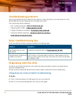
Страница 40: ...s Power On Self Test POST Troubleshoot using the LEDs See Diagnosing with the LEDs Link light does not light when a cable is connected Look for loose or obviously faulty connections If they appear to be OK make sure the connections are snug If that does not correct the problem try a different cable Diagnosing with the LEDs The first section shows LED patterns on the switch that indicate problem co...

Страница 41: ... are snug 2 Try power cycling the switch by unplugging and plugging the power cord back in 3 If the Power LED is still not on verify that the AC power source works by plugging another device into the outlet Or try plugging the switch into a different outlet or try a different power cord If the power source and power cord are OK and this condition persists the switch power supply may have failed Ca...

Страница 42: ...re secure Verify the connected device and switch are both powered on and operating correctly Verify that the connected devices comply with the appropriate IEEE 802 3 standard including transmission of the Link signal If the other procedures do not resolve the problem try using a different port or a different cable LED Patterns for PoE Troubleshooting Press the LED Mode button to put the switch int...

Страница 43: ...either 1 Pressing the recessed front panel reset button with a blunt object for less than 5 seconds or 2 via the web interface Restoring to Factory Defaults If you forget the switch IP address or password you can restore the factory default configuration by pressing the Reset button To execute the factory default reset on the switch perform these steps Procedure 1 Using a small thin tool with blun...

Страница 44: ...lass 4 2SFP 124W Switch JL681A 10 x 10 x 1 73 25 4 x 25 4 x 4 39 cm 4 66 lb 2 11 kg Aruba Instant On 1930 24G 4SFP SFP Switch JL682A 8 72 x 17 42 x 1 73 22 15 x 44 25 x 4 39 cm 5 32 lb 2 41 kg Aruba Instant On 1930 24G PoE Class 4 4SFP SFP 195W Switch JL683A 10 42 x 17 42 x 1 73 26 5 x 44 25 x 4 39 cm 7 71 lb 3 5 kg Aruba Instant On 1930 24G PoE Class 4 4SFP SFP 370W Switch JL684A 10 42 x 17 42 x ...

Страница 45: ... Power 0 dB no fan Aruba Instant On 1930 48G PoE Class 4 4SFP SFP 370W Switch JL686A Pressure 40 6 Power 63 2 dB Safety Complies with EN60950 1 2006 A11 2009 A1 2010 A12 2011 IEC60950 1 2005 Am1 2009 CSA22 2 No 60950 1 07 2nd UL60950 1 2nd EN 60825 1 2007 IEC 60825 1 2007 Class 1 Standards Laser safety information Technology Compatible with these IEEE standards EN IEC standard compliance SFP Laser...

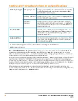
Страница 46: ... information Note on 1000BASE T Cable Requirements The Category 5 networking cables that work for 100BASE TX connections should also work for 1000BASE T as long as all four pairs are connected But for the most robust connections you should use cabling that complies with the Category 5e specifications as described in Addendum 5 to the TIA 568 A standard ANSI TIA EIA 568 A 5 Because of the increased...

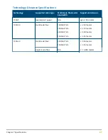
Страница 47: ...tances 1000 T twisted pair copper N A up to 100 meters 1000 SX multimode fiber 160 MHz km 200 MHz km 400 MHz km 500 MHz km 2 220 meters 2 275 meters 2 500 meters 2 550 meters 1000 LX multimode fiber 400 MHz km 500 MHz km 2 550 meters 2 550 meters single mode fiber N A 2 10 000 meters Chapter 7 Specifications 47 ...

Страница 48: ...se https community arubainstanton com Security bulletins https www arubanetworks com support services security bulletins End user license agreement https www arubainstanton com eula Support contact numbers https www arubainstanton com contact support 48 Aruba Instant On 1930 Installation and Getting Started Guide Support information ...

Отзывы: