background image

Aruba 303H Series Hospitality Access Point 

| Installation Guide

5

Figure 4  

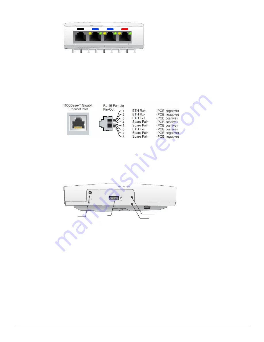
Bottom 

The E0 port, located at the bottom of the access point is 10/100/1000 Base-T, auto-sensing, MDI/MDX wired-

network uplink connectivity RJ45 port. It supports IEEE 802.3af/802.3at PoE as a standard Powered Device (PD) 

from Power Sourcing Equipment (PSE), such as a midspan injector or a network infrastructure that supports PoE.

The E1-E3 ports, located at the bottom of the access point are 10/100/1000 Base-T auto-sensing, MDI/MDX 

wired-network downlink connectivity RJ45 ports. These ports are used to provide secure network connectivity to 

wired devices when physically linked using an Ethernet cable. Refer to 

Figure 5


for port pin-out information.

Additionally, the E3 port supports PoE-out functionality, and is capable of supplying up to 13W to PSE when the 

access point is operating in 802.3at PoE mode, or powered by a DC source.

Figure 5  

Gigabit Ethernet Port Pin-Out

USB Interface

The AP-303H access point is equipped with 

USB port that is compatible with cellular modems and Bluetooth 

Low Energy (BLE) dongles. When active, the USB port can supply up to 5W/1A


to a connected device.

Figure 6  

Side

Push Button

The push button located on the right side of the device can be used to reset the access point to factory default 

settings or turn off/on the LED display. 

To reset the access point to factory default settings:
1. Power off the access point.
2. Press and hold the push button using a small, narrow object, such as a paperclip.
3. Power-on the access point without releasing the push button. The system status LED will flash within 5 

seconds.

4. Release the push button.
The system status LED will flash again within 15 seconds indicating that the reset is completed. The access 

point will now continue to boot with the factory default settings.

To turn off/on the system status LED:
During the normal operation of the access point, press the push button using a small, narrow object, such as 

a paperclip. The system status LED will be turned off/on immediately.

E0

E0

E3

E2

E1

48V

600mA

AC/DC 
power socket

USB port

Reset button

Security Screw Lock

Содержание AP-303H Series

Страница 1: ...ies Dual wireless transceivers IEEE 802 11a b g n ac operation as a wireless access point IEEE 802 11a b g n ac operation as a wireless air monitor Compatibility with IEEE 802 3af at PoE Central manag...

Страница 2: ...e operating mode of the access point s radios as shown in Table 2 Color State Meaning Off Device is powered off Green solid Device is ready fully functional Green blinking1 Device is booting not ready...

Страница 3: ...lor State Meaning Off Meets one of the following conditions both radios are disabled device is powered off Green solid Both radios enabled in access mode Green blinking1 One radio enabled in access mo...

Страница 4: ...t allows for direct management of the device when connected to a laptop or serial console For pin out details refer to Figure 3 Figure 3 Console Port Pin out Ethernet Ports The AP 303H access point is...

Страница 5: ...The AP 303H access point is equipped with a USB port that is compatible with cellular modems and Bluetooth Low Energy BLE dongles When active the USB port can supply up to 5W 1A to a connected device...

Страница 6: ...h vendor specific options Identifying Specific Installation Locations When installing the AP 303H access point must be secured to an Aruba approved wall or to a desk mount kit This access point should...

Страница 7: ...to a variety of electrical gang boxes Use the steps below to install your AP 303H 1 Begin by removing the existing data wall plate if applicable 2 Remove any existing RJ45 connectors typically snap in...

Страница 8: ...n 5 Insert the two included machine screws and tighten them to secure the mounting bracket 6 Connect any required cables to the back of the AP 303H 7 Align the mounting slots on the back of the AP 303...

Страница 9: ...ronmental Specifications For additional specifications on this product please refer to the product data sheet at www arubanetworks com safety_addendum Electrical Ethernet 100 1000 Base T auto sensing...

Страница 10: ...Exposure Statement This equipment complies with FCC RF radiation exposure limits This equipment should be installed and operated with a minimum distance of 10 63 inches 27cm between the radiator and y...

Страница 11: ...27 4500 Fax 408 227 4550 a Hewlett Packard Enterprise company 11 Aruba 303H Series Hospitality Access Point Installation Guide Proper Disposal of Aruba Equipment Dispose of Aruba products per local re...

Отзывы: