2
Aruba 7005 Series Controller
| Installation Guide
Figure 2
Back Panel of the Aruba
7005
Controller
Ethernet Ports
The 7005 controller is equipped with four 10/100/ 1000BASE-T Gigabit Ethernet ports (0 to 3). Gigabit
Ethernet uses all eight wires and each pair is bi-directional, which means, the same pair is used for both
data transmission and data reception.
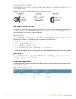
Figure 3
illustrates the Gigabit Ethernet port pin-out for a RJ-45
connector. The pins paired on a 10/100/1000BASE-T Gigabit Ethernet port are: 1/2, 3/6, 4/5, and 7/8.
Figure 3
Gigabit Ethernet Port Pin-Out
Ethernet Port LEDs
Each 10/100/1000BASE-T Ethernet port is equipped with two LEDs allowing you to monitor the status and
activity on the port. These LEDs provide basic monitoring of the status and activity of each port.
LINK/ACT
: Placed on the left side of the port, and displays the link status and activity of the port.
STATUS
: Placed on the right side of the port, and displays the status of the port based on the
information displayed by this LED changes based on LCD’s mode.
The following table describes the LED behavior for each mode:
1000Base-T Gigabit
Ethernet Port
RJ-45 Female
Pin-Out
Signal Name
1
2
3
4
5
6
7
8
BI_DC+
BI_DC-
BI_DD+
BI_DD-
BI_DA+
BI_DA-
BI_DB+
BI_DB-
Function
Bi-directional pair +C
Bi-directional pair -C
Bi-directional pair +D
Bi-directional pair -D
Bi-directional pair +A
Bi-directional pair -A
Bi-directional pair +B
Bi-directional pair -B
In the Aruba 7005 controller, the orange numbering on port 0 indicates that it is PoE powered and the gray
numbering on ports 1, 2, and 3 indicate that they are non-PoE.
Table 1
10/100/1000BASE-T Ethernet Port LEDs
LED
Function
LCD Mode
Indicator
Status
LINK/ACT
Link status
N/A
Green (Solid)
Link has been established
Green (Blinking)
Port is transmitting or receiving data
Off
No link on port


