


66
In “RS232” position of DIP switches, RS232 communication with an external device is performed through
the standard DB9 socket shown above. If DIP switches are in “INTERNAL” position, communication through
the standard socket is turned off and routed to an internally connected device. For example, if an ML100
Port Multiplexer has been installed in the UPS, standard DB9 socket is not used for RS232 communication,
instead, the two ports, COM1 and COM2 on the ML100 can be used for external communication
simultaneously.
8.2 Serial Communication Cable
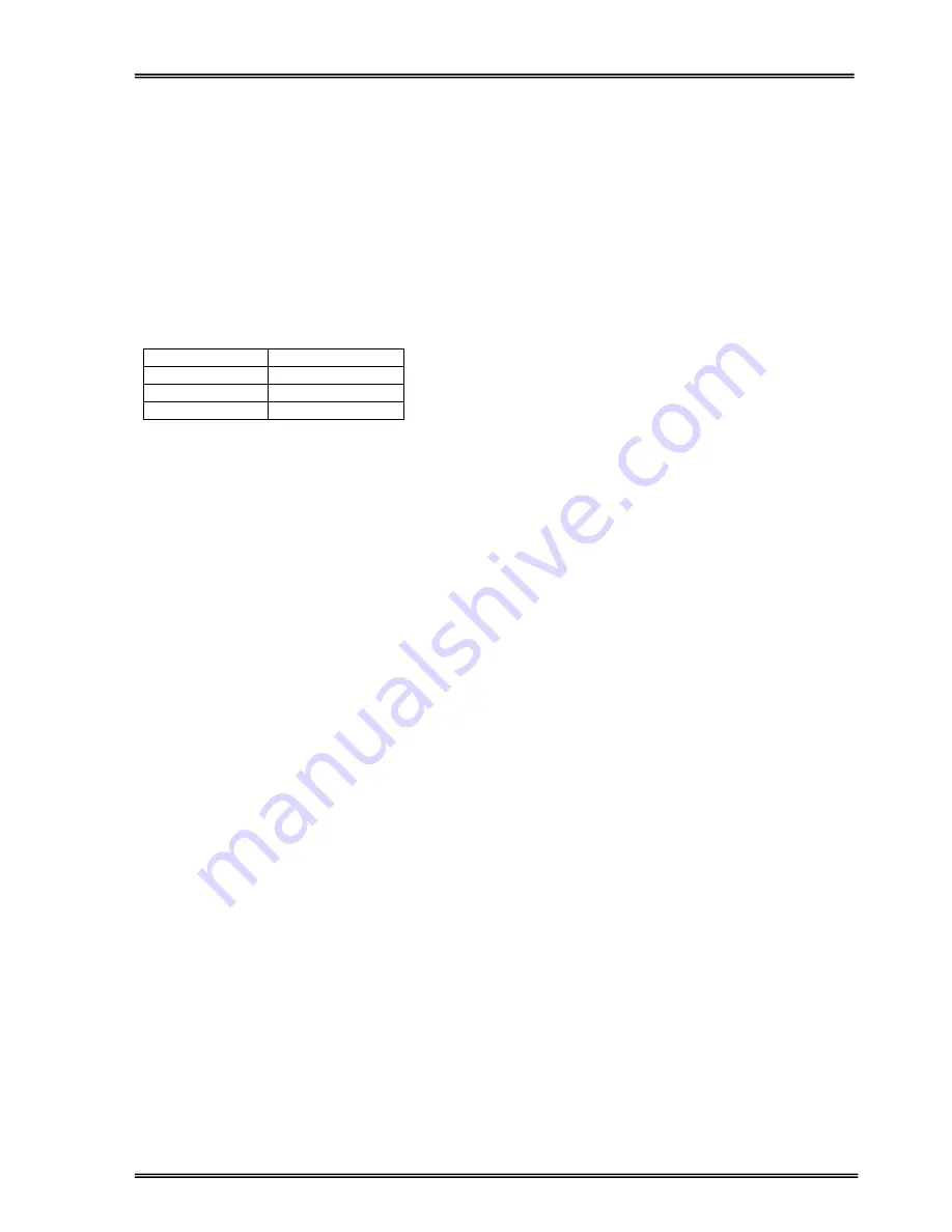
The maximum length for RS232 communication cable should be 25 meters. Cable connector pin
configuration is as follows:
UPS side
PC side
9 Tx
2 Rx
7 Gnd
5 Gnd
6 Rx
3 Tx
For remote panel and UPS connection the same pin configuration is valid.
8.3 Modem Connection
A ARTonPlus Series UPS can be controlled through a normal telephone line by means of a remote
operator connected through a PC with modem device, who performs a phone call to the UPS connected
number. So the operator can see all parameters and control the UPS (if permitted from OPTIONS MENU).
8.3.1 Hardware Configuration
All requirements for modem connection are as follows:
PC with modem
WINDOWS 98
Available UPS control software (T-MON)
NULL modem which is connected to UPS
In order to perform this function a PC with UPS control software and an external or internal modem device
connected to telephone line are needed.
A NULL modem device, configured according to NULL and auto answer modes, when installed in the UPS
and, once programmed, following a telephone call of the PC-embedded modem, will connect the UPS to
the telephone line.
8.3.2 Functioning Principle
The remote operator, by means of a PC and a modem device and using the remote connection function of
the control software, calls the UPS through the number to which this is connected.
The NULL modem device, connected to the UPS, will answer the call and convert the data coming from
UPS’s serial port on to the telephone line. This way all measurements and controls allowed by the RS232
serial port can be carried out.
Содержание ARTon Plus series
Страница 1: ...SERVICE TRAINING NOTES ARTon Plus SER S UPS 10 15 20 30 40 kVA 3 Faz Giri 3 Faz k...
Страница 2: ......
Страница 13: ...9 Figure 1 4 2 IGBT Rectifier...
Страница 14: ...10 Figure 1 4 3 Transformerless 3 Phase Inverter...
Страница 15: ...11 Figure 1 4 4 ARTonPlus series UPS Basic Diagram...
Страница 21: ...17 Figure 1 5 3 PFC3P R1 Board...
Страница 23: ...19 Figure 1 5 4 IPMD3P Board...
Страница 28: ...24 Figure 1 5 5 P3MC R5 Board...
Страница 31: ...27 Figure 1 5 6 ADVS01 R1 Board...
Страница 33: ...29 Figure 1 5 7 SDXC300 R1 Board...
Страница 36: ...32 Figure 1 5 9 ITF3 R2 Board...
Страница 39: ...35 Figure 1 5 11 OPS3 Board...
Страница 40: ...36...
Страница 41: ...37...
Страница 42: ...38...
Страница 48: ...44 K3 K1 K2 K2 Figure 2 3 ARTonPlus series 10 15 20 KVA Internal Battery Connections 2x30 60x12V 7Ah...
Страница 73: ......
Страница 74: ...1 AGKK7080 01 2008...