PST & PSS & PSH SERIES PROGRAMMABLE POWER SUPPLY
PROGRAMMER MANUAL
1
1 .
INTRODUCTION
In the modern automatic measurement system, communication
between equipments and computers is essential. The measured
procedures can be varied with users’ testing programs, therefore, the
programmable power supply can be operated remotely from an
instrument controller or computer across the RS232 interface (optional)
or GPIB (optional ).
Interface selection and setup
The GPIB address can be changed in normal operation condition. P ress
[SHIFT] key and [LOCAL] key on the front panel, in which t he last
transmitting interface settings will be displayed. Select interface and
press [ENTER ], then select the ba ud rate (or GPIB address) and press
[ENTER] to confirm the setting by using the knobs. Finally, select
“save” and press [ENTER] to store the setup.
2. CONNECTING THE PROGRAMMABLE POWER
SUPPLY VIA GPIB INTERFACE
The GPIB interface capabilities:
The GPIB interface of the programmable power supply corresponds to
the standard of IEEE488.1 -1987, IEEE488.2-1992 and SCPI-1994. The
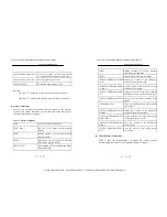
GPIB interface functions are listed as follows:
SH1(Source Handshake)
: The power supply can transmit multilane
messages across the G PIB.
AH1(Acceptor Handshake) : The power supply can receive multilane
messages across the GPIB.
T6(Talker)
: Talker interface function includes basic
talker, s erial poll, and unaddress if MLA
capabilities, without talk only mode
function.
PST & PSS & PSH SERIES PROGRAMMABLE POWER SUPPLY
PROGRAMMER MANUAL
2
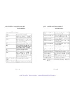
L4 (Listener)
: The power supply becomes a listener
when the controller sends its listen
address with the ATN (attention) line
asserted. The power supply does not
have listen only capability.
SR1 (Service Request)
: The power supply asserts the SRQ
(Service request) line to notify the
controller when it requires service.
RL1 (Remote/Local)
: The power supply responds to both the
GTL(Go t o Local) and LLO(Local Lock
Out) interface messages.
PP0 (Parallel Poll)
: The power supply has no Parallel Poll
interface function.
DC1 (Device Clear)
: The power supply has Device clear
capability to return the device to power
on status.
DT0 (Device Trigger)
: The power supply has no Device Trigger
interface function.
C0 (Controller)
: The power supply can not control other
devices.
Notes for GPIB installation
When the programmable power supply is set up with a GPIB system,
please check the following things :
l
Only a maximum of 15 devices can be connected to a single GPIB
bus.
l
Do not use more than 20m of cable to connect devices to a bus.
l
Connect one device for every 2m of cable used.
l
Each device on the bus needs a unique device address. No two
devices can share the same device address.
Artisan Technology Group - Quality Instrumentation ... Guaranteed | (888) 88-SOURCE | www.artisantg.com


