


11
20-740/745
RF MULTIPLEXER MODULE
pickering
Section 2
20-745 R.F. Multiplexer Module
2.1 20-745 Multiplexer Features
•
Quad 8 to 1, Dual 16 to 1 and Single 32 to 1 Multiplexer with up to 2000MHz Bandwidth
•
Available in both 50 and 75
Ω
Versions
•
Choice of Front Panel Mounted Connectors: SMB, Type 43 and MMC Connectors
•
Front Panel LED Indicators
•
Built-In Self Test
•
Ideal Building Block for Large R.F. Switching Networks
•
75
Ω
Version Suitable for Telecoms and Video Switching
2.1.1 Description
A High Density 1500MHz Multiplexer arranged as a Quad 8 to 1 or Dual 16 to 1 or Single 32 to 1 configuration, all with
excellent Insertion Loss, VSWR & Isolation, available in a choice of 50 or 75
Ω
versions with SMB, Type 43 or MMC
Connectors.
This module is a higher density version of type 20-740 with the automatic termination function removed, the RF
performance specification is similar. It is an equivalent to the 20-730-902 balanced 120
Ω
multiplexer.
Applications for the 20-745 include routing high frequency signals to and from oscilloscopes, analysers, signal generators
and synthesizers, telecoms tributary switching, video/audio switching and switching high frequency logic signals.
Larger multiplexer/matrix switching networks may be constructed by interconnecting individual modules, see section 4
for further details.
2.1.2 Operation
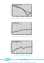
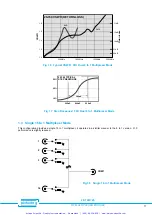
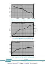
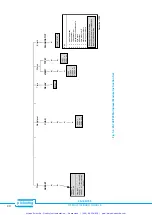
This module is factory configured as a quad 8 to 1 multiplexer, see fig 2.4. Performance figures are given in table 2.1.
However it may also be configured (using dip switches and jumper cables) as a 16 to 1 or 32 to 1 multiplexer. Please note
that the R.F. performance for these configurations will be to a slightly reduced specification, please refer to table 2.1 for
further details.
Self-Test is performed both at power up and at any other time either manually or under program control. In the unlikely
event of relay failure the front panel will indicate a fault. The diagnosis - including the position of the suspect relay - will
be indicated using the DIAGNOSTIC? command.
This is a double height module and must be mounted into a double height (6U) case.
2.1.3 Front Panel
The module front panels are illustrated in Section 6, they include:
Status Display, 4 LED Indicators:-
Power LED.
Connected to power system supply.
Active LED.
On whenever one or more switches are closed. For a list of all active switches use the VIEW?
command.
Self-Test LED. Active when self-test in progress.
Error LED.
Indicates that error found during self-test.
Self-Test Button. Press to initiate a self-test. While in progress the “Self-Test” LED will be on, if a failure is detected
then the “Error” LED will be set on permanently. Use the DIAGNOSTIC? command to find the exact cause of any failure,
refer to section 5 for further details. NB: Self-Test button will only respond when module is inactive.
Width and Dimensions. All modules conform to the 6U height (262mm) Eurocard standard and are 160mm deep,
panel width is 1.8 Inches (45.7mm).
2.1.4 20-745 Module Model Numbers
The following table lists the standard options available with the RF multiplexer module:-
Model Number
Bandwidth
Connector
Impedance
20-745-501
1500MHz
SMB Version
50
Ω
20-745-521
1000MHz
MMC Version
50
Ω
20-745-701
1500MHz
SMB Version
75
Ω
20-745-711
1500MHz
Type 43 Version
75
Ω
20-745-721
1000MHz
MMC Version
75
Ω
When ordering a configuration code should be specified, the module will then be preconfigured in Quad 8, Dual 16 or Single 32
channel mode. Other connector types are available to order.
Artisan Scientific - Quality Instrumentation ... Guaranteed | (888) 88-SOURCE | www.artisan-scientific.com


