background image

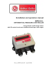
Installation and operation manual

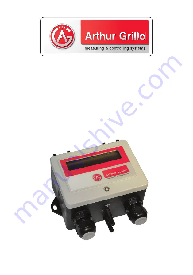
DPC310

 - 

DIFFERENTIAL PRESSURE CONTROLLER

Doc.-no.: DPC310_01_EN  Issue: 01/2018

Low pressure multi range sensor

with PI-control mode and multifunctional input and output

Содержание DPC310

Страница 1: ...Installation and operation manual DPC310 DIFFERENTIAL PRESSURE CONTROLLER Doc no DPC310_01_EN Issue 01 2018 Low pressure multi range sensor with PI control mode and multifunctional input and output ...

Страница 2: ...te de www sensor store de 01 2018 DPC310_001_EN This documentation including all parts is protected by copyright Any utili sation or modification other than permissible under the strict limitations of copyright law is prohibited and liable to prosecution without the approval of the Arthur Grillo GmbH This applies in particular to duplications trans lations microfilming and storage and processing i...

Страница 3: ...onnections 4 4 Schematic view inside 4 5 Zero adjustment 5 Operation 5 1 How to configure the DPC310 5 1 1 Measuring mode 5 1 2 Control mode 5 2 Adjustable parameters 5 3 Threshold calculation 5 4 Function alarm output 5 4 1 Control mode 5 4 2 Measuring mode 5 5 Extern 0 10V dc input 5 5 1 Extern setpoint via 10V input 5 5 2 Temperatur controlled setpoint 5 6 Measuring range selection 6 Maintenanc...

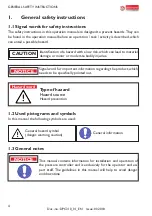
Страница 4: ...rial damage or minor or moderate bodily injuries CAUTION 1 2 Used pictograms and symbols In this manual the following symbols are used General hazard symbol danger warning caution Signal word for important information regarding the product which needs to be specifically pointed out NOTICE Hazard word Type of hazard Hazard source Hazard prevention 1 3 General notes This manual contains information ...

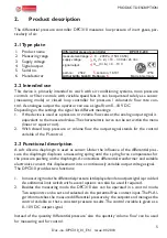
Страница 5: ... the output signal stands for the control variable of the PI control 2 3 Functional description A soft silicone diaphragm is used as sensor Under the influence of the differential pres sure the diaphragm displaces a measuring spring until the spring force compensates for the pressure pushing on the diaphragm A contactless differential transformer and suitable electronics convert this displacement ...

Страница 6: ...aterial damage Read the manual carefully before installation and operation Only experienced staff may connect the device and bring it into operation CAUTION The device is position depended The DPC310 must be mounted vertically NOTICE 3 1 Dimensions All dimensions in mm 3 2 Wall mounting 1 Hold the DPC310 against the wall Mark the mounting holes 2 Drill mounting holes for properly sized screws 3 Pu...

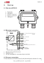
Страница 7: ...r Anschluss 0 10 Vdc Eingang dry contact open Setpoint 1 close Setpoint 2 10 30 Vdc or 24 Vac 15 electronic excitation GND 0 10 Vdc output GND alarm output maximum customer circuit 30 Vdc 30 mA 1 2 3 4 5 6 7 8 9 10 ΔP DPC310 alarm output open collector 0 10 Vdc input GND 1 Unscrew screws of the front cover 2 Open front cover 3 Use M16 cable glands for connecting wiring to terminals 4 3 Pressure co...

Страница 8: ...8 Doc no DPC310_01_EN Issue 01 2018 ...

Страница 9: ...9 Doc no DPC310_01_EN Issue 01 2018 ...

Страница 10: ...10 Doc no DPC310_01_EN Issue 01 2018 OPERATION ...

Страница 11: ...11 Doc no DPC310_01_EN Issue 01 2018 OPERATION ...

Страница 12: ...12 Doc no DPC310_01_EN Issue 01 2018 OPERATION ...

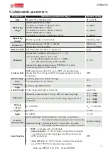
Страница 13: ...ure from 0 up to 100 of measuring range Volume flow from 2 up to 100 of measuring range k factor is considered OFF Alarm delay time switching delay time adjustment range 1 60 seconds or 2 15 minutes 10 s Switching logic switching logic MIN or MAX MAX Contact logic contact logic active high or active low active high Setpoints differential pressure from 0 up to 100 of measuring range volume flow fro...

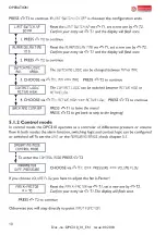
Страница 14: ...r The open collector output has two different states High resistive to disable an external circuit Low resistance to connect an external circuit with maximum load of 30Vdc 30 mA 5 4 1 Control mode In order to recognize the limits of control the alarm output in control mode refers to set maximum output voltage maxUout MaxUout can be set in menu item output voltage The device requires a minimum pres...

Страница 15: ... or 2 15 min In the basic state this value is set to 10 seconds 2 switching logic here you have the possibility to set the limit values to MAX or MIN At MAX an alarm is triggered when the measured value exceeds the limit value at MIN the alarm is triggered when the limit value is exceeded 3 Contact logic the rest state or the switching state of the open collector output can be set differently Acti...

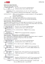
Страница 16: ...cted voltages as new setpoints To keep the input signal stable for at least 0 1V the signal range is divided into 50 incre ments of 0 2V each For a measuring range of 500 Pa the 50 steps correspond to 10 Pa per 0 2V 0V at the input is not detected as a 0 Pa setpoint but rather ignored As a result no con stant input signal is required whereby the device can be initialized once and used the set valu...

Страница 17: ...is the starting value of the compensation The next input temperature t2 corresponds to the final value of the compensation The following menu item compensated setp corresponds to the setpoint value for the full compensation Following states are possible tmess t1 The setpoint is not changed tmess t2 The maximum compensation is reached and the setpoint is equal to the set value for compensated setpo...

Страница 18: ...ring range The measuring ranges can be switched with keyT1 The displayed value is then used and stored in the EEPROM All other entries now refer to this value Differential pressure controller DPC310 200 Measuring range 1 0 200 Pa or 0 0 8 InH2O Measuring range 2 0 150 Pa or 0 0 6 InH2O Measuring range 3 0 100 Pa or 0 0 4 InH2O Measuring range 4 0 50 Pa or 0 0 2 InH2O Differential pressure controll...

Страница 19: ...e intended use Disasters due to external influences and force majeure 8 Troubleshooting 9 Disposal Dispose of parts so as not to endanger human health or the environment Follow the laws in the country of use for disposing of electronic components and devices during disposal Description Activity Display does not show anything Check electrical connection Measurement stays zero Function test with a s...

Страница 20: ...M16x1 5 screw terminal Electronic protection against reversed polarization 10 30 Vdc 24 Vac 15 approx 8 mA 10 Vdc approx 10 mA 24 Vdc 0 10 V 10 Vdc Imax 0 5 mA Rmax 20 kΩ 24 Vdc Imax 4 0 mA Rmax 2 5 kΩ Open Collector max 30 V 30 mA 0 10 V multifunctional input extern setpoint 0 10 V input is related to measuring range temp compensated setpoint 0 10 V input is related to 30 0 70 0 C LCD Display 2 x...

Страница 21: ...3 correction 1 2011 06 Electromagnetic compatibility EMC Part 6 2 Generic standards Immunity for industrial environments DIN EN 61000 6 3 2011 09 Electromagnetic compatibility EMC Part 6 3 Generic standards Emission standard for residential commer cial and light industrial environments You can order the Declaration of Conformity at Arthur Grillo GmbH Am Sandbach 7 40878 Ratingen Phone 49 21 02 47 ...

Страница 22: ...re controller DPC310 1000 Measuring range 1 0 1000 Pa or 0 4 0 InH2O Measuring range 2 0 750 Pa or 0 3 0 InH2O Measuring range 3 0 500 Pa or 0 2 0 InH2O Measuring range 4 0 250 Pa or 0 1 0 InH2O 2543 Differential pressure controller DPC310 6000 Measuring range 1 0 6000 Pa or 0 24 0 InH2O Measuring range 2 0 4000 Pa or 0 16 0 InH2O Measuring range 3 0 3000 Pa or 0 12 0 InH2O Measuring range 4 0 200...

Отзывы: