background image

ARTEX PRODUCTS / ACR ELECTRONICS, INC 

DESCRIPTION, OPERATION, INSTALLATION AND MAINTENANCE MANUAL 

ELT 345 (P/N: A3-06-2880) 

Page 28 of 58 

25-62-35 

SUBTASK 25-62-35-750-004 

I.


121.5 MHz Power Output Measurement – Item 5c   

1)


Connect the measuring device as specified in Figure 6 Performance Test Setup on page 27. 

2)


Activate the ELT, if necessary, by placing the control switch in the ON position.   

3)


Wait three minutes. 

4)


Read the displayed amplitude for 121.5 MHz. The amplitude must be within the minimum specified for 121.5 
MHz in Table 3 on page 22 at the terminal output. 

SUBTASK 25-62-35-750-005 

J.


406 MHz Frequency Measurement – Item 5d   

CAUTION: 

POWER OUTPUT IS APPROXIMATELY 5 WATTS. ENSURE THAT ADEQUATE ATTENUATION IS 
INSERTED BETWEEN THE ELT AND THE MEASURING INSTRUMENT. 

1)


Connect the measuring device as specified in Figure 6 Performance Test Setup on page 27. 

2)


Activate the ELT using the local ELT switch.   

3)


Wait three minutes. 

4)


Measure the frequency after the stabilization period. The frequency must be within the tolerance specified in 
Table 3 on page 22. 
NOTE: 

The exact 406 MHz frequency is printed on the ELT product label.   

SUBTASK 25-62-35-750-006 

K.


406 MHz Power Output Measurement – Item 5e   

CAUTION: 

POWER OUTPUT IS APPROXIMATELY 5 WATTS. BE SURE ADEQUATE ATTENUATION IS 

INSERTED BETWEEN THE ELT AND THE MEASURING INSTRUMENT.   

1)


Connect the measuring device as specified in Figure 6 Performance Test Setup on page 27. 

2)


Activate the ELT, if necessary, by placing the control switch in the ON position.   

3)


Wait three minutes. 

4)


Read the displayed amplitude of the 406 MHz burst that follows the three-minute wait period. The amplitude 

must be within the minimum specified for 406 MHz in Table 3 on page 22, at the output terminal. 

5)


Deactivate the ELT by placing the control switch in the “ARM” position. 

SUBTASK 25-62-35-750-007 

L.


Current Draw Test – Item 5f   

CAUTION: 

EXERCISE EXTREME CAUTION TO AVOID A SHORT CIRCUIT CONDITION OF THE BATTERY 
PACK CONNECTIONS. THIS WILL BLOW A FUSE IN THE BATTERY PACK, FORCING 

REPLACEMENT. 

CAUTION: 

ALL ON STATE CURRENT MEASUREMENTS MUST BE MADE WITH THE ANTENNA OUTPUT 
TERMINATED IN 50 OHMS.   

CAUTION: 

THE 406 MHZ SIGNAL PULSES EVERY 50 SECONDS (APPROXIMATE) AND MAY DRAW UP TO 
4 AMPERES FOR ½ SECOND. MANY METERS WILL NOT RESPOND THIS FAST OR READ THIS 

TYPE OF WAVEFORM ACCURATELY. BECAUSE OF THIS, ACR ELECTRONICS DOES NOT 
RECOMMEND MEASURING THE 406 MHZ BURST CURRENT. 

1)


Verify the ELT control switch is in the “ARM” position. 

2)


Disconnect the battery pack from the ELT. 

3)


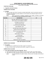
Install test fixture 8104 in the power circuit in series between the battery pack connector and the ELT connector 

(see Figure 7 Current Draw Test Setup).   

Содержание ELT 345

Страница 1: ...ce Manual Y1 03 0282 Rev E This manual includes data for the following equipment Component Labeled Part No Purchase Part No Emergency Locator Transmitter A3 06 2880 8100 2 Wire Remote Switch A3 06 2759 8304 Mounting Tray A3 06 2882 8323 Installation Kit 455 7423 455 7423 Antenna w Coax black A3 06 2892 1 8324 in kit Cable Coaxial BNC to BNC 6 ft 611 6013 04 611 6013 04 ELT 345 Kit 8102 8102 Batter...

Страница 2: ...contained herein ACR Electronics is not liable in the event of incidentals special consequential or any other damages in connection with or arising from furnishing performance or use of this manual Reproduction of this publication or any portion thereof by any means is prohibited For further information contact Sales ACR Electronics 5757 Ravenswood Rd Fort Lauderdale FL 33312 6603 Telephone 954 98...

Страница 3: ...N INSTALLATION AND MAINTENANCE MANUAL ELT 345 P N A3 06 2880 Page 3 of 58 25 62 35 RECORD OF REVISIONS REVISION CHANGE DATE REVISION CHANGE DATE A W I 05 EN 05 Aug 06 15 B ECO 16144 Sept 15 15 C ECO 16240 Jan 19 16 D ECO 16376 May 9 16 E ECO 16385 Jun 15 16 ...

Страница 4: ...S ACR ELECTRONICS INC DESCRIPTION OPERATION INSTALLATION AND MAINTENANCE MANUAL ELT 345 P N A3 06 2880 Page 4 of 58 25 62 35 SERVICE BULLETIN LIST SERVICE BULLETIN NO ISSUE DATE SUBJECT MANUAL REV NO MANUAL REV DATE ...

Страница 5: ... Sept 15 15 Installation 37 Sept 15 15 List of Figures 9 Jan 19 16 38 Sept 15 15 Introduction 10 Sept 15 15 39 Sept 15 15 11 Sept 15 15 40 Sept 15 15 12 Sept 15 15 41 Sept 15 15 13 Sept 15 15 42 Sept 15 15 14 Sept 15 15 43 Sept 15 15 15 Sept 15 15 44 Dec 10 15 16 Sept 15 15 45 Dec 10 15 Description and Operation 17 Sept 15 15 46 Sept 15 15 18 Sept 15 15 47 Dec 10 15 19 Sept 15 15 48 Dec 10 15 20 S...

Страница 6: ... 11 C RTCA DO 160G Compliance 12 4 Frequency Allocation 13 A Application 13 B Discussion 13 5 List of Acronyms Abbreviations and Definitions 14 6 References 16 A Regulatory Documents 16 B Other Documents 16 DESCRIPTION AND OPERATION 17 1 Description 17 A Functional Overview 17 B System Components 18 2 Operation 20 A Overview 20 B Normal Operation 20 C Manual Activation 20 D ELT Reset 21 E Function...

Страница 7: ...wer Output Measurement Item 5e 28 L Current Draw Test Item 5f 28 M Digital Message Verification Item 5g 29 N ELT Reset Check Item 5h 30 O Installed Transmitter Antenna Test Item 6 30 P Antenna Test Item 7 31 Q Inspection and Test Documentation Item 8 31 3 Fault Isolation 31 A Self Test 31 B Troubleshooting 33 REMOVAL 34 1 ELT 34 A ELT Removal 34 2 Battery 35 A Battery Removal 35 3 Material or Equi...

Страница 8: ...nnections 49 G ELT Programming 49 H RS 232 Acceptable Nav Data 49 7 ELT Installation and Test 49 A Installation 49 B Harness ELT D Sub Plug Sealing 50 C Installation Documentation 51 8 Battery Pack Installation 51 A Battery Installation and Reinstallation 51 ILLUSTRATED PARTS LIST 53 1 Introduction 53 A Purpose 53 B IPL Usage Guide 53 2 Manufacturer Name and Address 53 A Ordering Information 53 AP...

Страница 9: ...0 Battery Pack Removal 35 Figure 11 ARTEX ELT 345 Outline Dimensions 39 Figure 12 ELT 345 Metal Strap Minimum Clearance Dimensions 40 Figure 13 Typical Mounting Tray Installation 41 Figure 14 A3 06 2892 1 Antenna Outlines and Dimensions 43 Figure 15 Remote Switch Outline and Dimensions 43 Figure 16 Buzzer Outline and Dimensions 44 Figure 17 Typical 2 Wire Installation for Unshielded Harness 45 Fig...

Страница 10: ...25 62 35 990 002 B Application 1 This manual constitutes supporting data documentation for the ARTEX ELT 345 including a Description and Operation b Test and Fault Isolation includes inspection criteria c Removal d Installation e Registration f Illustrated Parts List 2 In the United States the ARTEX ELT 345 must be installed and maintained in accordance with the requirements herein 14 CFR FAR Part...

Страница 11: ...al information please refer to the ARTEX web site at www acrartex com SUBTASK 25 62 35 990 002 B Battery CAUTION LITHIUM BATTERY SAFETY CONCERNS INCLUDE THE POSSIBILITY OF FIRE VENTING VIOLENTLY AND VENTING OF TOXIC GASES 1 The lithium battery packs used on the ARTEX ELT 345 are certified under TSO C142a NOTE The conditions and tests for TSO approval of this article are minimum performance standar...

Страница 12: ... RTCA DO 204A Requirements S C 8 0 Vibration X 9 0 Explosion Atmosphere Test Not Applicable R 10 0 Waterproofness Continuous Stream X 11 0 Fluid Susceptibility Not Applicable X 12 0 Sand and Dust Not Applicable X 13 0 Fungus Resistance Test Not Applicable S 14 0 Salt Fog Z 15 0 Magnetic Effect Test Z 16 0 Power Input Test A 17 0 Voltage Spikes Z 18 0 AF Susceptibility ZCX 19 0 Induced Signal Susce...

Страница 13: ...ss frequency band SUBTASK 25 62 35 990 002 B Discussion 1 The product identification label on each ELT specifies the transmission frequencies of the individual ELT The ARTEX ELT 345 transmits a frequency of 406 040 MHz Allocation of frequencies based on beacon population per specified frequency band is controlled by COSPAS SARSAT 2 The frequency references throughout this manual for the 406 MHz co...

Страница 14: ...site for the International COSPAS SARSAT Program http www cospas sarsat int en D SUB RECEPTACLE D type shaped subminiature connectors connector for low voltage current signals and electrical currents DER Designated Engineering Representative An individual qualified and designated by the FAA to approve or recommend approval of technical data to the FAA DRIP LOOP Extra wire length used to form a U s...

Страница 15: ... radio waves RTCA Radio Technical Commission for Aeronautics Organization that makes recommendations for airworthiness refer to http www rtca org aboutrtca asp for more information RTV A rubbery silicon based adhesive typically used to prevent vibration problems and water intrusion SAR Search and Rescue SCREEN ROOM Refers to a room designed to block RF signals such that the broadcast of an ELT pla...

Страница 16: ...7 Part 87 Aviation Services g FAR Part 43 Maintenance Preventive Maintenance Rebuilding and Alteration h FAR Part 91 General Operating and Flight Rules i TSO C126b 406 MHz Emergency Locator Transmitter ELT j TSO C142a Non Rechargeable Lithium Cells and Batteries 4 Canada a CAR Part V Airworthiness b CAR Part VI General Operating and Flight Rules 5 COSPAS SARSAT a C S G 005 Cospas Sarsat Guidelines...

Страница 17: ...shut down automatically The 121 5 MHz transmitter homer transmitter will continue to operate until the batteries are exhausted which is at least 50 hours 5 The location accuracy of the 406 MHz transmitter is typically 3 km If position information is extracted from the aircraft navigation system the accuracy improves to approximately 100 meters standard or national location protocol 6 The 406 MHz d...

Страница 18: ...y is made of high impact fire resistant polycarbonate polyester plastic The tray is fabricated from aluminum with a stainless steel holding strap See Figure 1 Figure 1 ARTEX ELT 345 Beacon and Mounting Tray 2 The cockpit mounted remote switch assembly includes a status LED and control switch The switch allows the operator to manually activate and reset the ELT for testing see Figure 2 Figure 2 Rem...

Страница 19: ...an audible alert when the ELT is active see Figure 3 Figure 3 Buzzer 4 The battery pack for the ARTEX ELT 345 consists of two D size Lithium Manganese Dioxide cells see Figure 4 Figure 4 Battery Pack Assembly 5 There is only one type of antenna that is approved for use with the ARTEX ELT 345 see Figure 5 This antenna is ARTEX part A3 06 2892 1 Figure 5 Antennas ...

Страница 20: ...pit remote switch must be changed from ON to ARMED If activation is from the G switch the switch position must first be set to ON then changed to ARMED NOTE The ELT g switch CANNOT be disarmed or disabled from the cockpit Cockpit operation is limited to activating and resetting the ELT 6 A warning buzzer is required by TSO C126b to indicate ELT activation when the aircraft is not operating The buz...

Страница 21: ...0 TASK 25 62 35 870 803 3 Specifications SUBTASK 25 62 35 870 001 A Environmental and Physical 1 Table 2 lists the environmental and physical specifications of the ELT 345 CRITERIA PARAMETER CHARACTERISTIC Temperature Storage 55 C to 85 C Operating 20 C to 55 C Mechanical Vibration 10 g 5 Hz to 2 000 Hz Shock 500 g for 4 ms Crashworthiness 100 g for 23 ms Humidity 95 for 50 hours Penetration 55 lb...

Страница 22: ... MHz 3K20A3X Modulation 406 MHz Bi Phase L G1D 121 5 MHz Amplitude Modulation A3X Transmitter Duty Cycle 406 MHz 440 or 520 ms 1 approximately every 50 seconds 5 121 5 MHz Continuous Peak Effective Radiated Power EIRP 406 MHz EIRP 5 W 37dBm for 24 hrs 20 C to 55 C 121 5 MHz EIRP 50 mW 17 dBm for 50 hrs 20 C to 55 C Occupied Bandwidth 406 MHz 20 KHz max 121 5 MHz 25 KHz max Spurious Emissions 406 M...

Страница 23: ... 406 MHz 1 5 1 Max Polarization Vertical Monopole Radiation Pattern Omnidirectional RF Power Handling 10 Watts CW Weight 0 19 lbs 0 09 kg Coax Cable RG 142 0 5dB 1 dB Insertion Loss Connector BNC Female Dimensions Base to Tip 23 4 in 594 mm NOTE The ARTEX recommended coaxial cable Part No 611 6013 04 6 ft complies with the minimum and maximum cable insertion losses quoted above If the installer ha...

Страница 24: ...ng and improper operation NOTE ARTEX recommends using www 406Test com to ensure the ELT 345 is testing through the satellite during annual inspections and initial installations SUBTASK 25 62 35 990 002 B Canada 1 CAR Part VI Standard 625 Appendix C requires the ELT to be inspected at intervals not exceeding 12 months 2 All maintenance and testing shall be performed in accordance with the requireme...

Страница 25: ...ion 4 G Switch Functional Check 5a 121 5 MHz Frequency Measurement 5b Audio Modulation Check 5c 121 5 MHz Power Output Measurement 5d 406 MHz Frequency Measurement 5e 406 MHz Power Output Measurement 5f Current Draw Test 5g Digital Message Verification 5h ELT Reset Check 6 Installed Transmitter Test 7 Antenna Test 8 Inspection and Test Documentation Table 5 ELT Inspection Checklist SUBTASK 25 62 3...

Страница 26: ...owing conditions are true a After use in an emergency b After an inadvertent activation of unknown duration c When the total of all known transmissions exceeds one hour d On or before battery replacement expiration date NOTE The new expiration date for replacing the battery must be legibly marked on the outside of the transmitter and entered in the aircraft maintenance record SUBTASK 25 62 35 750 ...

Страница 27: ...tion of the ELT 2 Place the ELT in an RF enclosure or screen room to prevent RF emissions 3 For final airworthiness verification use the ELT s own battery pack as the power source for these measurements An alternate power source can be used where lengthy servicing other than the performance tests is anticipated Expired battery packs can be used if the airworthiness performance of the battery pack ...

Страница 28: ...PPROXIMATELY 5 WATTS BE SURE ADEQUATE ATTENUATION IS INSERTED BETWEEN THE ELT AND THE MEASURING INSTRUMENT 1 Connect the measuring device as specified in Figure 6 Performance Test Setup on page 27 2 Activate the ELT if necessary by placing the control switch in the ON position 3 Wait three minutes 4 Read the displayed amplitude of the 406 MHz burst that follows the three minute wait period The amp...

Страница 29: ... on page 51 Hints a Short the meter leads at the meter with a banana plug type jumper lead to protect the fuses in the meter b Using a spectrum analyzer as a load device detect when the 406 MHz burst has occurred SUBTASK 25 62 35 750 008 M Digital Message Verification Item 5g 1 Use a beacon reader such as ARTEX P N 453 1000 453 2000 8700 or 8701 to test the transmitted digital message 2 Connect th...

Страница 30: ...this test as the aircraft Com Transceiver is very sensitive and may pick up a weak signal even if the antenna is disconnected from the ELT Please ensure that the ELT is switched off before the 406 MHz burst is initiated approximately 50 seconds after activation 5 Locate the radio approximately 20 to 30 from the antenna 6 Initiate a self test by momentarily pressing the cockpit remote switch into t...

Страница 31: ... the ELT inspection and testing was satisfactorily completed 2 For aircraft operating under Canadian authority following satisfactory completion of performance testing the date on which the test was performed shall be marked on the ELT external casing in a legible and permanent manner TASK 25 62 35 810 801 3 Fault Isolation SUBTASK 25 62 35 810 001 A Self Test 1 The self test checks certain critic...

Страница 32: ...e antenna checked by factory 5 No position data present long message protocol only Error is suppressed for short messages Aircraft navigation system OFF Turn on navigation system Verify that ELT and navigation system baud rates match NMEA baud is 4800 AB Protocol baud is 9600 Faulty system interface wiring or connections Check integrity of wiring and connections 6 G Switch loop between pins 5 and ...

Страница 33: ...t Verify integrity of all crimp and solder connections ELT will not turn off Turn ELT OFF using control switch If ELT turns off Defective remote switch harness reset circuit wiring Check wiring continuity and repair as necessary Defective remote switch Replace remote switch If ELT does not turn OFF using control switch ELT defective Remove battery pack to disable ELT and return ELT to factory for ...

Страница 34: ... ELT SUBTASK 25 62 35 010 001 A ELT Removal 1 See Figure 9 ELT Removal Sequence Figure 9 ELT Removal Sequence 2 Disconnect the antenna coax cable NOTE Check the coax cable center conductor pin which is prone to retracting into the connector housing 3 Remove remote switch harness D sub plug 4 Open the metal strap 5 Slide the ELT up and out and away from the mounting tray ...

Страница 35: ... AND CONNECTOR PINS ON THE BOARD CAUTION TAKE CARE NOT TO DAMAGE THE SHORT POWER CABLE WHICH CONNECTS THE BATTERY PACK TO THE ELT TOP COVER 1 See Figure 10 Battery Pack Removal Figure 10 Battery Pack Removal 2 Place the ELT on a surface with the D sub receptacle side up 3 Remove the four screws from the top cover 4 Carefully separate the top cover from the ELT taking care not to put strain on the ...

Страница 36: ...rial Authorization 1 Upon receipt of such notice ACR Electronics Inc will issue a Return Material Authorization RMA number which then authorizes return of the material or equipment to the following address Repair and Overhaul ACR Electronics Inc 5757 Ravenswood Road Fort Lauderdale FL 33312 6603 USA Phone 954 981 3333 Fax 954 983 5087 a Failure to obtain a RMA number and provide the details listed...

Страница 37: ...tion information NOAA will provide registrants with proof of registration and change of registration postcards SUBTASK 25 62 35 990 002 B TSO C126b Paragraph D 1 TSO approval of the ELT does not constitute installation approval All ELT installations are subject to field approval for a given airframe by either an approved FAA DER or FAA FSDO For installations outside the US contact your local civil...

Страница 38: ... more than 1 0 meters from the mounting location 2 DO 182 6 2 2 b recommends that a To maximize the probability of the ELT transmitting a detectable signal after a crash all ELT system components which must survive a crash intact e g transmitter and external antenna should be attached to the airframe in such a manner that the attachment system can support a 100 g load ELT weight x 100 ELT antenna ...

Страница 39: ...E MUST BE EXTREMELY RIGID MOUNTING AN ELT DIRECTLY TO THE AIRCRAFT SKIN FOR EXAMPLE IS UNACCEPTABLE CAUTION AVOID LOCATING THE ELT WHERE IT WILL BE SUBJECTED TO UNPROTECTED EXPOSURE TO HARSH CHEMICAL FLUIDS SUCH AS DEICING COMPOUNDS THESE TYPES OF CHEMICAL FLUIDS CAN PROMOTE CRACKING AND FRACTURING OF THE ELT MOUNTING FRAME AND HOUSING COMPONENTS BY DEGRADING THE STRUCTURAL INTEGRITY OF THESE COMP...

Страница 40: ...s 1 Select a suitable location for the ELT mounting tray see Figure 11 ARTEX ELT 345 Outline Dimensions on page 39 and Figure 12 ELT 345 Metal Strap Minimum Clearance Dimensions above 2 Mount the ELT as far aft as practical but where it can be easily retrieved for maintenance 3 Additional installation guidance may be found in AC 43 13 2 Chapter 2 28 which specifically addresses ELT installations ...

Страница 41: ...rrow on the tray is within 10 of the longitudinal axis of the aircraft and pointing in the direction of flight 4 Mark and drill the four mounting holes with a 19 or 4 25 mm drill Refer to Figure 11 on page 39 for the mounting hole pattern 5 Install the mounting tray as shown in Figure 13 installation kit 455 7423 NOTE The use of substitute mounting hardware is acceptable provided the hardware used...

Страница 42: ...ticle on or in a specific type or class of aircraft must determine that the aircraft installation conditions are within the TSO standards TSO articles must have separate approval for installation in an aircraft CAUTION ARTEX CANNOT VERIFY APPROPRIATE ANTENNA SELECTION PER EACH AIRFRAME MANY CONSIDERATIONS MUST BE EVALUATED DURING THE ANTENNA SELECTION PROCESS SUCH AS DYNAMIC STATIC LOADING CERTAIN...

Страница 43: ...as part of some ELT kits Figure 14 A3 06 2892 1 Antenna Outlines and Dimensions TASK 25 62 35 450 803 4 Remote Switch SUBTASK 25 62 35 450 001 A Location NOTE The ELT 345 must be installed using a 2 wire remote switch ARTEX P N A3 06 2757 Note that the 2 wire remote switch does not require a connection to the aircraft power to operate 1 Select a suitable switch location in the cockpit The switch n...

Страница 44: ...MMENDED DUE TO THE POTENTIAL FOR DISTRACTION THE BUZZER PRODUCES A LOUD SIREN TYPE SOUND WHEN THE ELT IS ACTIVATED SINCE THE BUZZER OPERATES IN TANDEM WITH THE COCKPIT LED IT WOULD ONLY SERVE AS A REDUNDANT WARNING INDICATOR IN THE COCKPIT 1 Select a suitable location for the buzzer NOTE The buzzer may be located anywhere in the aircraft however the recommended location is near the ELT as the buzz...

Страница 45: ... CAUTION TO PREVENT INADVERTENT ELT ACTIVATION OR POSSIBLE COMPONENT DAMAGE DO NOT CONNECT THE HARNESS TO THE ELT OR COCKPIT REMOTE SWITCH UNTIL ALL POWER AND GROUND WIRING CONNECTIONS ARE COMPLETED AND VERIFIED 1 The following wiring and grounding considerations and recommendations are applicable a Minimum 22 AWG wire size b Shielding is recommended to help prevent EMI and RF interference c Use h...

Страница 46: ...priate wiring diagram 3 Strip approximately 0 15 in 3 mm of insulation from the remote switch end of each of the harness cable wires Dress and tin the bare wires to prevent the strands from fraying during terminal crimping operations 4 Support for the harness wiring can be referenced in AC 43 13 1 Chapter 11 9 through 12 5 Install the buzzer connecting wires NOTE The buzzer ground and the ELT grou...

Страница 47: ...ARTEX PRODUCTS ACR ELECTRONICS INC DESCRIPTION OPERATION INSTALLATION AND MAINTENANCE MANUAL ELT 345 P N A3 06 2880 Page 47 of 58 25 62 35 Figure 19 Remote Switch Harness Arrangement ...

Страница 48: ...e shield or ground pin for composite airframe installations see Figure 18 Typical 2 Wire Installation for Shielded Harness on page 46 for composite airframe wiring diagram 6 Solder a short jumper wire G switch loop between pins 5 and 12 of the harness D sub receptacle CAUTION THE ELT WILL NOT AUTOMATICALLY ACTIVATE IF THE JUMPER G SWITCH LOOP IS NOT PROPERLY INSTALLED IN THE ELT D SUB RECEPTACLE 7...

Страница 49: ...ion for Unshielded Harness on page 45 Figure 18 Typical 2 Wire Installation for Shielded Harness on page 46as appropriate SUBTASK 25 62 35 990 002 G ELT Programming NOTE Programming is performed by customer if so equipped or through a programming sheet supplied to ACR Electronics with an ELT order For information on ELT programmers and training please contact ACR Electronics 1 ELTs that are serial...

Страница 50: ... remote switch was activated This may result in ELT transmissions or setting the ELT into a monitoring condition This may result in the ELT exhibiting battery runtime in excess of regulations To avert this condition after the harness connection is complete the installer shall activate the self test on the installed unit This action will need to be performed whenever the harness is disconnected and...

Страница 51: ...N ACTIVITIES TAKE PARTICULAR CARE TO AVOID TOUCHING THE EXPOSED CIRCUIT BOARD AND CONNECTOR PINS ON THE BOARD 1 This subtask applies to reinstallation of an existing battery that was removed for inspection and testing as well as fitting a new battery 2 See Figure 22 Battery Pack Installation Figure 22 Battery Pack Installation 3 Remove the old O ring from the front assembly and discard Apply Lubri...

Страница 52: ...rness 11 Place the manual switch in the ON position and monitor the ELT s operation with a communication receiver tuned to 121 5 MHz If the ELT can be heard move the switch back to the OFF or ARMED position Verify that there is no 7 flash error code displayed on the status LED see applicable ELT Manual for details on testing ELT 12 Enter in the airframe logbook the date of the installation of the ...

Страница 53: ...the item number assigned to the part c Refer to the associated parts list and find the item number in the Fig Item column 2 If the part number is known a Refer to the parts list and find the part in the Part column b Note the figure number and item number assigned to the part c Refer to the illustration in the applicable IPL figure to find attaching hardware and related assembly parts 3 In cases w...

Страница 54: ...mbly and Installation ITEM PART DESCRIPTION QTY 01 A3 06 2880 ARTEX ELT 345 Main Assembly 1 03 A3 06 2883 Lithium Battery Pack 1 05 201 0402 Screw 6 32 x 7 8 PHL Truss SS 4 06 A3 06 2882 Mounting Tray 1 201 0810 Screw PHL 8 32 x 5 8 SS 4 246 0008 Washer Flat SS 8 4 241 0832 Nut Hex 8 32 x SS 4 A1 20 1798 Label LiMnO2 ARTEX ELT 345 1 Table 8 Main Assembly Components ...

Страница 55: ...SS 4 247 0400 Washer internal lock SS 4 4 241 0440 Nut 4 40 x hex SS 4 591 0428 Label ELT Cautionary Use Advisory 1 151 5009 Plug 9 pin 1 151 6628 Terminal crimp female 0 062 dia 4 02 150 1130 Conn D sub 15 pin Female Solder cups 1 03 150 1127 Housing D sub 15 pin grommet thumbscrews 1 850 0814 Sealant strip D sub receptacle 2 201 0810 Screw PHP 8 32 x 5 8 SS 4 241 0832 Nut 4 246 0008 Washer 4 04 ...

Страница 56: ...ICS INC DESCRIPTION OPERATION INSTALLATION AND MAINTENANCE MANUAL ELT 345 P N A3 06 2880 Page 56 of 58 25 62 35 Figure 25 Antennas ITEM PART DESCRIPTION QTY 01 A3 06 2892 1 RAMI Whip Ant black w 6 Coax Cable 1 Table 10 Antennas 1 ...

Страница 57: ...ft navigation system and programmed with a location protocol 5 If the beacon is reprogrammed to a new protocol aircraft tail number different country etc the 15 Hex ID changes and the beacon requires relabeling TASK 25 62 35 990 802 2 Registration SUBTASK 25 62 35 990 001 A Responsibility 1 It is the responsibility of the aircraft owner to register the ELT a If an ELT is moved to a different aircr...

Страница 58: ...ation agency 2 Specific registration web sites and information may be found at a The ARTEX products web site at www acrartex com which has links to on line registration sites and also a link to registration forms and instructions for a number of countries b The NOAA ELT registration web site at beaconregistration noaa gov where an ELT may be directly registered in the United States NOTE NOAA may a...

Отзывы: