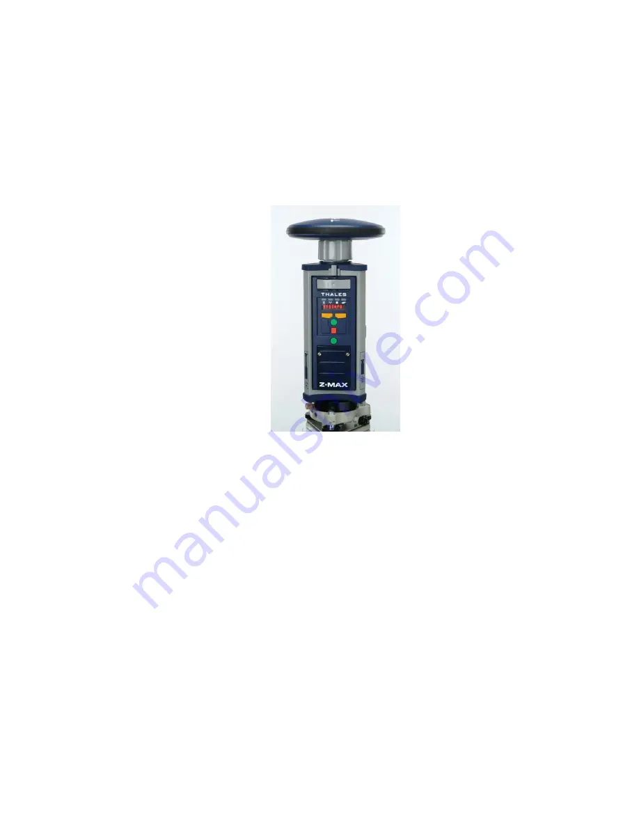
Getting Started with Z-Max
Z-Max GPS Surveying System
Thales Navigation, Inc.
471 El Camino Real
Santa Clara, California 95050 USA
www.thalesnavigation.com
Страница 1: ...Getting Started with Z Max Z Max GPS Surveying System Thales Navigation Inc 471 El Camino Real Santa Clara California 95050 USA www thalesnavigation com...
Страница 2: ...d with Z Max is an easy to read booklet to help you identify and assemble the basic parts of the system The additional documentation section of this guide provides references to other system documenta...
Страница 3: ...Important items will have part numbers on them and can be cross referenced with the Shipping Document Z Max GPS Receiver Module P N 800963 GPS Antenna Module P N 800961 Power Module and Charger Max R...
Страница 4: ...or cellular modem For non real time systems this device seals the communications bay from moisture The V Module looks similar to a Communications Module so be sure to verify the part number Cables for...
Страница 5: ...4 Z Max Getting Started Tripod Mounting Tribrach adapter P N 101199 HI Measurement Tool P N 701083 HI Measurement Plate P N 204456...
Страница 6: ...Vortex UHF Antenna Module P N 800962 x0 Base Radio and Antenna The rover UHF radio antenna Thales U Link Transmitter P N 80098x xx Base Radio Data power Cable Antenna Pacific Crest UHF Transmitter P...
Страница 7: ...6 Z Max Getting Started RTK Pole P N 110977 Mounting Bracket P N 204439 The fixed height survey pole Bracket used to mount the data collector to the survey pole...
Страница 8: ...800979 Max RF Adapter P N 800978 Provides a comfortable way for a person to carry the Z Max on their back Provides a cable interface on the survey pole Used when the Z Max is in Backpack Configuratio...
Страница 9: ...F are identical except for color coding the GPS RF cable is coded black Cables are required when the Z Max is in Backpack Configuration The UHF RF cable that connects the Range Pole RF Adapter to the...
Страница 10: ...odule for at least 2 3 hours to make sure that your Power Module is charged enough to get you through this booklet Charging the Power Module overnight is recommended If you don t completely charge you...
Страница 11: ...he Main receiver Module at the port marked POWER as shown in Figure 3 3 Attach the GPS Antenna Module Attach the GPS Antenna Module to the GPS Receiver Module as shown in Figure 4 For the Z Max to tra...
Страница 12: ...5 Front panel orientation The features of the front panel are shown in Figure 6 These include 4 LED indicator lights RTK Solution Communication Data Log and SV Power front panel display control keys f...
Страница 13: ...conds power is on and blink green several times between each red blink one SV is tracked for each green blink Check the Data Log LED The Data Log LED should blink green every 20 seconds to indicate th...
Страница 14: ...up and execution a troubleshooting guide Field Application Software Guide This manual covers the field application software that runs on the handheld computer data collector This manual covers the fol...
Страница 15: ...615 3980 or 408 615 3981 International Fax 408 615 5200 Email professionalsupport thalesnavigation com Europe Middle East and Africa EMEA plus International Monday thru Friday 8 00 A M to 6 00 P M GMT...