ARTEX DGL-1, Руководство по установке и обслуживанию
ARTEX DGL-1 - качественный продукт для вашего дома. Установочное и обслуживающее руководство доступно для загрузки бесплатно с нашего сайта. Руководство включает в себя подробные инструкции по установке и техническому обслуживанию продукта. Надежность и удобство - вот что делает ARTEX DGL-1 лучшим выбором для вас.
Поделиться
Скачать


Отзывы:
Нет отзывов
Похожие инструкции для DGL-1

CHILL MAT PLUS
Бренд: Targus Страницы: 10

CB-USB20PL
Бренд: Vantec Страницы: 4

QLE2460
Бренд: Qlogic Страницы: 2
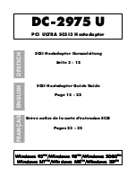
DC-2975 U
Бренд: Dawicontrol Страницы: 32

QUICK V0113
Бренд: Emos Страницы: 24

VAC-12HUC
Бренд: Marshall Amplification Страницы: 6

100 Image
Бренд: WMS Страницы: 16

Enercell 273-356
Бренд: Enercell Страницы: 1
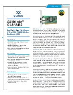
SANblade QLA 2462
Бренд: Qlogic Страницы: 2

USB312SAT3
Бренд: StarTech.com Страницы: 2

WL-BUI112-10I
Бренд: Inteltronic Страницы: 1

AirLive HP-3000E
Бренд: Air Live Страницы: 39

NBARF9003FBK
Бренд: nedis Страницы: 2

NBARF9005FBK
Бренд: nedis Страницы: 2

NBARF9004FBK
Бренд: nedis Страницы: 2

ACA960
Бренд: Targus Страницы: 8

2173
Бренд: Lenze Страницы: 18

XETB1001 - 85 MBit/s Powerline Network Adapters
Бренд: NETGEAR Страницы: 2


