


8
IL6000 Chassis Installation and Operations Manual
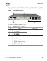
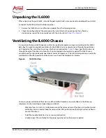
IL6000 Chassis
Installing the IL6000 Chassis
You can place the IL6000 chassis on a flat surface as a free-standing unit, rack mount it in a standard 19 inch
equipment rack, or mount the chassis to a wall. As you position the IL6000 for installation, ensure that there is
enough space in the back of the chassis to install and cable the various power supply and function modules.
Note:
Before installing your IL6000 chassis, see the
InfinityLink Media Transport Platform Data Sheet
for
a detailed description of the IL6000 product specifications including environmental
requirements that you must adhere to when installing the chassis and power supply modules.
The section contains the following topics:
•
Installing the IL6000 as a Free-standing Chassis (page 8)
•
Installing the Chassis in a Rack (page 8)
•
Installing the IL6000 as a Free-standing Chassis
When installing the IL6000 chassis as a free-standing chassis, follow these requirements:
•
The surface must be flat, clean, and in a safe location. The chassis must not be installed on the floor. In
addition to increasing the risk of being damaged, placing the chassis on the floor increases the risk of
dust building up in the chassis and causing problems related to overheating.
•
The area provides a 2 inch (5 cm) clearance on all four sides of the chassis for proper ventilation (see
“Ventilating the IL6000 Chassis” section on page 7
) and accessing the power switches, status LEDs,
module slots, and cable connections.
Installing the Chassis in a Rack
Flush-mounting the chassis sets the front edge of the unit even with the front edge of the rack. When
installing multiple chassis in a rack, no vertical space between the units is required. The only limit to the
number of chassis that you can place in a rack is the height of the rack.
Caution
If the system is installed in a closed or multi-unit rack assembly, the operating ambient
temperature of the rack environment might be greater than the room ambient
temperature. Therefore, consideration should be given to installing the equipment in an
environment compatible with the maximum ambient temperature specified for the
system.
Содержание InfinityLink IL6000
Страница 1: ...WWW ARTEL COM Manual Installation and Operations Manual INFINITYLINK IL6000 Chassis...
Страница 2: ...ii IL6000 Chassis Installation and Operations Manual...
Страница 4: ...iv IL6000 Chassis Installation and Operations Manual...
Страница 11: ...IL6000 Chassis Installation and Operations Manual xi...
Страница 31: ...18 IL6000 Chassis Installation and Operations Manual...
Страница 33: ...Index Index 2 IL6000 Chassis Installation and Operations Manual...
Страница 34: ......


