background image

7

6

2-2-1. Interface Connector


     <9 Pin Serial>                                                       <USB “B” Type>


                            <Ethernet>

9Pin Serial Interface

Pin

Signal

I/O

Description

2

RXD

Input

Printer receive data line RS-232C level

3

TXD

Output

Printer transmit data line RS-232C level

4, 7

DTR

Output

Printer handshake to host line RS-232C level

5

GND

-

System Ground

6

DSR

Input

Data Send Ready

1,8,9

NC

-


USB Interface

Pin

Signal

I/O

Description

1

+5V

-

+5V

2

DATA-

-

Printer transmit data line 

3

DATA+

-

Printer transmit data line 

4

GND

-

System Ground


Ethernet Interface

PIN

SIGNAL

I/O

1

Data Out +

Output Data +

2

Data Out -

Output Data -

3

GND

Ground

4

Data IN +

Input Data +

5

Data IN -

Input Data -

6

N.C

7

N.C

8

N.C

This equipment is indoor use and all the communication wirings are limited to inside of the building.

2-2-2. Cash Drawer Connector

The printer can operate two cash drawers with a 6 pin RJ-11 modular connector. 
The driver is capable of supplying a maximum current of 1.0A/24VDC for 510ms or less when not 
printing.

PIN

SIGNAL

DESCRIPTION

1

Signal GND

-

2

Drawer kick-out drive signal 1

Output

3

Drawer open/close signal

Input

4

+24V

-

5

Drawer kick-out drive signal 2

Output

6

Signal GND

-

Caution : To avoid an overcurrent, the resistance of the drawer kick-out solenoid must be 
               24

 Ω 

or more.

Содержание AP-8220 USE

Страница 1: ...AP 8220 USE Rev A 10 14 All specifications are subject to change without notice Receipt Printer User s Manual MODEL AP 8220 USE...

Страница 2: ......

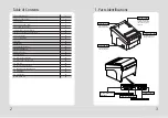
Страница 3: ...Cutter Specifications 18 9 3 Interface 18 9 4 Electrical Characteristics 18 9 5 Environmental Requirements 19 9 6 Reliability 19 9 7 Certification 19 10 Command List 20 Table of Contents 1 Parts Ident...

Страница 4: ...are damaged or missing please contact your dealer for assistance The Printer CD Roll Paper Adaptor optional Interface Cable optional 2 Setting Up the Printer For connection to a host computer For conn...

Страница 5: ...L I O 1 Data Out Output Data 2 Data Out Output Data 3 GND Ground 4 Data IN Input Data 5 Data IN Input Data 6 N C 7 N C 8 N C This equipment is indoor use and all the communication wirings are limited...

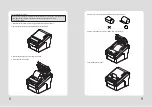
Страница 6: ...ff power switch 1 Make sure that the printer is not receiving data Otherwise data may be lost 2 Open the paper roll cover by pushing down the cover open button 3 Remove the used paper roll core if the...

Страница 7: ...ff 2 Remove the screw from the DIP switch cover Then take off the DIP switch cover as shown in the illustration below 3 Turn screw with drivers to a direction until paper is released from the cutter 2...

Страница 8: ...hether the printer is operating properly Also with this user can check following options or status of the printer Control circuit Printer mechanism Printing quality ROM version Interface setting This...

Страница 9: ...e ASCII characters that correspond to the codes Hecadecimal Dump 1B 21 00 1B 26 02 40 40 1B 25 01 1B 63 34 00 1B c4 41 42 43 44 45 46 47 48 ABCDEFGH A period is printed for each code that has no ASCII...

Страница 10: ...garding print head cleaning as the print head is very hot during printing turn off the printer power and wait approximately 10 minute before start 3 When cleaning the print head take care not to touch...

Страница 11: ...ul about installing the printer in an area where there is noise 3 Take the appropriate measure to protect against electrostatic AC line noise etc 9 5 Environmental Requirements 1 Operating Temperature...

Страница 12: ...or s to output paper end signals 36 ESC c 4 Select paper sensor s to stop printing 37 ESC c 5 Enable disable panel buttons 38 ESC d Print and feed paper n lines 39 ESC p General pulse 10 Command List...

Отзывы: