background image

16

5986

5986

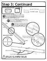
Finished Length

118 1/8”   300,0 cm

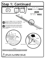
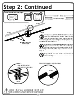
Slide parts together until fi ve (5) holes align.

Place bolt thru center hole only.

Slide parts together 

until eight (8) holes align.

5986

Rear Angle

2

(QTY: 9)

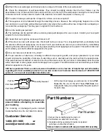
You will need for this page:

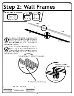
Step 2: Wall Frames

Overlap two (2) 

Rear Wall Channels

 so that 

eight (8) holes align as shown. Insert a bolt and 

nut through each hole. Check that the fi nished 

length of the 

Assembly

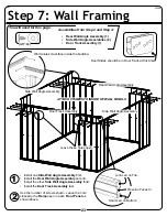
 is 118 1/8” ( 300,0 cm) set 

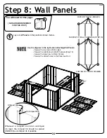
aside for use in Step 10.

1

2

Overlap two (2) 

Rear Wall Angles

 so that fi ve 

(5) holes align as shown. Insert a bolt and nut 

through the center hole. Check that the fi nished 

length of the 

Assembly

 is 118 1/8” ( 300,0 cm) set 

aside for use in Step 7.

16AW

5986

10389

10389

10389

 10389

Rear Channel

2

Содержание LM101267S

Страница 1: ...ns Roof Edge to Roof Edge Width Depth Height Interior Dimensions Wall to Wall Width Depth Height Door Opening Width Height Approx Size Storage Area 10 x 12 115 Sq Ft 693 Cu Ft 123 1 4 145 3 4 77 7 8 118 1 4 140 1 2 76 5 8 55 1 2 65 3 0 m x 3 6 m 10 7 m 2 19 6 m3 313 1 cm 370 2 cm 197 8 cm 300 4 cm 356 9 cm 194 6 cm 141 0 cm 165 1 cm For proper base construction see page 12 Base Size 121 x 143 1 4 ...

Страница 2: ...of of the building When using a step ladder make sure that it is fully open and on even ground before climbing on it Do NOT attempt to assemble your building on a windy day The large panels can catch the wind like a sail causing them to be whipped around making construction difficult and unsafe Do NOT attempt to assemble your building before double checking that you have all the parts indicated on ...

Страница 3: ...a windy day Be careful on wet or muddy ground Use Teamwork Two or more people are required to assemble your building One person can hold the parts or panels in place while the other person fastens them together and handles the tools This makes the process of assembling your building faster and safer Tools and Materials Here is a list of some basic tools and materials you will need to assemble your...

Страница 4: ...collapses Note Most instruction manuals provide a warning note at the beginning of the installation step for corner panels stating that the remainder of the building assembly requires multiple hours and more than one person Do not continue beyond this point if you do not have enough time or help to complete the assembly that day A partially assembled building can be severely damaged by even light ...

Страница 5: ...it is square Also try loosening the roof beams to give more play and flexibility Non alignment can also occur if your building is not level You can raise corners and shim under them to make it level Check that the panels are installed in the proper location The building should not be permanently anchored until the complete unit is assembled otherwise you will not be able to make adjustments for squ...

Страница 6: ...ain your shed s attractive appearance for years Q How do I take care of dents in my shed A Proper selection of shed size including a sufficient door opening width and proper placement of your shed should minimize the possibility of damage If a dent does occur carefully push the dent out from the opposite side If the paint has been scratched or removed touch up the area as soon as you notice it Imme...

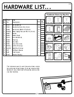
Страница 7: ...65109 Acorn Nut 8 32 4 8 67468 Peak Cap 2 9 66769 Door Slide 4 10 66382 Lower Door Guide 4 11 66183L Left Roof Trim Cap 2 12 66183R Right Roof Trim Cap 2 13 5971 Roof Beam Bracket 4 14 6228 Track Support 2 15 67545 Weather Stripping 1 Key No Part No Part Description Qty List The fasteners used in each step are shown actual size at the top of each page If you are unsure which fastener to use hold i...

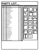
Страница 8: ...Corner Panel 4 15 6640 Right Roof Panel 2 16 6641 Left Roof Panel 2 17 6868 Ridge Cap 1 18 6869 Ridge Cap 2 19 8934 Ramp 1 20 8936 Rear Floor Frame 2 21 9366 Door Track 2 22 9367 Front Floor Frame 2 23 9370 Door Jamb 2 24 9374 Front Wall Panel 2 25 10389 Rear Wall Channel 2 26 10390 Side Wall Channel 4 27 10392 Side Floor Frame 4 28 10393 Side Wall Angle 4 29 10408 Skylight Panel 2 30 10409 Roof P...
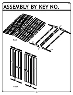
Страница 9: ...ASSEMBLY BY KEY NO 9 09AW 27 Walls Floor 27 27 27 20 20 22 22 19 13 13 13 13 13 13 13 13 13 13 14 14 14 14 24 24 23 23 3 3 11 21 21 28 28 28 28 5 5 26 26 26 26 25 25 ...

Страница 10: ...4 Doors 32 4 32 10 10 1 1 4 4 ASSEMBLY BY KEY NO 10 10AW Roof 2 2 33 33 31 31 31 31 31 31 31 31 12 12 12 12 15 15 16 16 29 29 30 30 18 18 17 9 9 9 9 8 8 6 6 7 7 ...

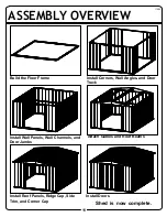
Страница 11: ...he Floor Frame Install Corners Wall Angles and Door Track Install Wall Panels Wall Channels and Door Jambs Attach Gables and Roof Beams Install Roof Panels Ridge Cap Side Trim and Corner Cap Install Doors 11AW Shed is now complete ...

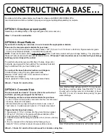
Страница 12: ...low instructions and diagram Construct frame using 10 penny galvanized nails Measure 16 24 40 6 cm 61 0 cm sections to construct inside frame see diagram Secure plywood to frame using 4 penny galvanized nails Allow 6 7 hours for construction OPTION 3 Concrete Slab The slab should be at least 4 10 2 cm thick It must be level and flat to provide good support for the frame The following are the recomm...

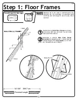
Страница 13: ...o use on every screw and bolt 10392 Side Floor Frame 4 Bolts thru Bottom Bolts thru Top Step 1 Floor Frames Overlap two 2 Side Floor Frames as shown and secure with four 4 bolts Two 2 bolts must enter from bottom 1 2 Assemble a second Side Floor Frame Assembly by repeating part 1 Check that the finished length of the Assemblies is 141 5 8 359 7 cm Set aside for use in Step 5 BUILD TWO 2 FRAMES 13AW...

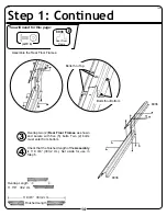
Страница 14: ...lts thru Bottom Bolts thru Top You will need for this page Step 1 Continued Overlap two 2 Rear Floor Frames as shown and secure with five 5 bolts Two 2 bolts must enter from bottom 3 4 Check that the finished length of the Assembly is 119 3 8 303 2 cm Set aside for use in Step 5 11 7 8 30 2 cm Overlap Length 14A ...

Страница 15: ... Drain holes must face outside the building Overlap the Ramp and two 2 Front Floor Frames so that four 4 holes align at each end as shown Insert four 4 screws in each end 5 6 Confirm that the drain holes are facing outside the building Check that the finished length of the Assembly is 119 3 8 303 2 cm Set aside for use in Step 5 8934 Ramp 1 9367 Front Floor Frame 2 7 3 8 18 7 cm Overlap Length QTY 8...

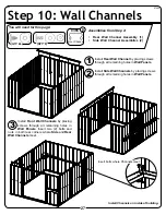
Страница 16: ...o 2 Rear Wall Channels so that eight 8 holes align as shown Insert a bolt and nut through each hole Check that the finished length of the Assembly is 118 1 8 300 0 cm set aside for use in Step 10 1 2 Overlap two 2 Rear Wall Angles so that five 5 holes align as shown Insert a bolt and nut through the center hole Check that the finished length of the Assembly is 118 1 8 300 0 cm set aside for use in St...

Страница 17: ...own Insert a bolt and nut through each hole Check that the finished length of the Assembly is 140 3 8 356 6 cm set aside for use in Step 10 3 4 Overlap two 2 Side Wall Angles so that holes align as shown Insert a bolt and nut through the hole Check that the finished length of the Assembly is 140 3 8 356 6 cm set aside for use in Step 7 5 Repeat Parts 1 2 to build a second set of each assembly QTY 18...

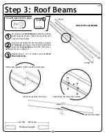
Страница 18: ...d for this page Finished Length 142 3 8 361 6 cm Step 3 Roof Beams Overlap two 2 Roof Beams so that the bottom slots align as shown Insert six 6 bolts and nuts as shown below 1 3 Repeat parts 1 2 to build a second Roof Beam Assembly 2 Insert two 2 bolts and nuts into slots on bottom of the Beam as shown Check that the finished length of the Assembly is 142 3 8 361 6 cm Set aside for use in Step 12 ...

Страница 19: ...hat bottom slots align but DO NOT INSERT BOLTS Next overlap two 2 more Roof Beams to form a second Roof Beam Assembly DO NOT INSERT BOLTS 4 6 Insert four 4 bolts and nuts into slots from bottom Check that the finished length of the Assembly is 142 3 8 361 6 cm Set aside for use in Step 12 5 Place both Roof Beam Assemblies back to back to form a Double Beam Insert ten 10 bolts and nuts as shown belo...

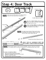
Страница 20: ...oor Slides Carefully bend the corner back into position Slides should be installed in Door Track prior to installation However if this step is overlooked or if the Slides need to be removed for maintenance the following procedure may be used Step 4 Door Track 2 Position the Door Slides in the Door Track Check that the finished length is 118 1 8 300 0 cm Set aside for use in Step 7 Align two 2 Door ...

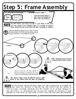
Страница 21: ...ont Corner Back Corner You will need for this page Step 5 Frame Assembly Assemble Floor Frame with two screws at each corner as shown At the front corners insert a bolt through the bottom of the Frame as shown 1 Do not continue beyond this point unless you have enough time to complete the shed today The remainder of assembly may take several hours and requires at least two people A partially assem...

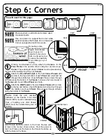
Страница 22: ...secure Be cautious when maneuvering and placing Panels Once Panels begin to go up it is important to be able to finish in a timely manner to reduce the possibility of wind damage to your building Bolt FRONT Leave these holes open 9374 9374 6633 6633 6633 6633 6627 6627 Double check the part numbers indicated on the Panels Front Wall Panels 9374 must be installed along front of building and Wall Pan...

Страница 23: ...ing Short Leg on Bottom Opening Faces In You will need for this page Door Slides should be in Door Track at this time Step 7 Wall Framing 2 Use the number of screws shown Leave the hole closest to the Ramp open in each Front Panel as shown above Install one Side Wall Angle Assembly first Install the Rear Wall Angle Assembly second Install the other Side Wall Angle Assembly third Install the Door Tr...

Страница 24: ...for this page Step 8 Wall Panels Lay out all Panels in the positions shown below 1 FASTEN TO WALL ANGLES FASTEN TO FLOOR FRAMES FASTEN TO WALL CHANNELS STEP 10 Use the diagram to the right when attaching Wall Panels Secure the top row to Wall Angles Secure the middle row to Wall Channels Step 10 Secure the lower row to Floor Frames Secure the circled holes to the Panel next to it 24AW NO HARDWARE ...

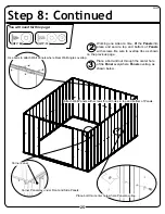
Страница 25: ...nel Attach Wall Panels with screws thru all holes in top and bottom of Panels You will need for this page Step 8 Continued Working one side at a time lift the Panels into place and secure top and bottom of Panels with screws Be sure to overlap ribs as shown on the previous page 2 3 Place a bolt and nut through the center hole of the Panel everywhere Panels overlap as shown below 25AW ...

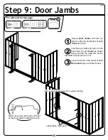
Страница 26: ...u will need for this page Step 9 Door Jambs Leave these holes open Secure Door Jambs with two 2 screws in the top and bottom of each Panel as shown 1 3 Leave the holes in the center of each Door Jamb open as shown below 2 Insert two 2 bolts and nuts into the back side of each Panel as shown below Secure the bolts with both a standard nut and an acorn nut 26AW ...

Страница 27: ... by placing screws through all remaining holes in Wall Panels 1 3 Install Front Wall Channels by placing screws through all remaining holes in Wall Panels Insert two 2 bolts and nuts in both rear corners where Side and Rear Wall Channels meet 2 Install Side Wall Channels by placing screws through all remaining holes in Wall Panels Front Channel 2 9365 Install Channels on inside of building 27AW QT...
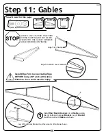
Страница 28: ...dge Trim MUST cover Gable edge Install Edge Trim to cover Gable Edge BEFORE doing ANY work with Gables Failure to do so could result in injury QTY 8 Leg of Roof Beam Bracket must face center of Gable as shown You will need for this page Step 11 Gables Install Roof Beam Brackets on all Gables using two 2 bolts and nuts per Bracket Leg of Bracket must face center of Gable as shown 1 28AW ...

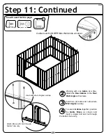
Страница 29: ...om hole only You will need for this page Step 11 Continued Working with one Gable at a time attach the Rear Gables to the Rear Wall Angle with screws 2 4 To secure Gables together position the Gable Brace as shown and insert a single bolt and nut through the bottom hole only 3 Insert two 2 bolts and nuts where Wall Angles overlap QTY 8 29AW ...

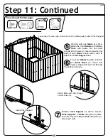
Страница 30: ...he two 2 holes closest to the peak of each Gable These will be used to attach the Track Support later 5 6 To secure Gables together position the Gable Brace as shown and insert a single bolt and nut through the bottom hole only 7 Position Track Support as shown Secure Track Supports to Gable using two 2 bolts and nuts Secure to Door Track using two 2 screws per side QTY 4 Gable Brace 1 6635 Track ...

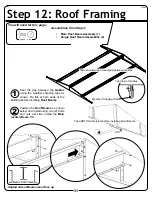
Страница 31: ...p View of Gables Tape should wrap around gap between Gables Step 12 Roof Framing Beam End Views Angled side of Beams must face up Seal the gap between the Gables using the weather stripping tape as shown Do this at both ends of the building before installing Roof Beams 1 2 Position the Roof Beams as shown below and install using two 2 bolts and nuts per side Install the Main center Beam first 31AW ...

Страница 32: ...crimped rib Crimped Rib Uncrimped Rib Be sure to carefully follow the Roof Panel Placement Order Diagram on this page 6640 6529 10409 6529 6641 6641 6529 10408 6529 6640 12 8 7 4 2 11 6 5 3 1 FRONT Roof Panel Placement Order If Roof Beam holes do not line up with Roof Panel holes shift the building from left to right If this does not help your building may not be level Shim the corners until holes...

Страница 33: ...ng to the diagram below Ensure that the ends of the Panels with the slotted holes are at the same end with the slot to the outside of the finished assembly 1 QTY 6 Place the Skylight Panel over the Roof Panel so that the three 3 sets of holes align 2 Fasten the two Panels together with bolts and nuts Make two 2 assemblies 3 Slot Slot 10409 10408 ...

Страница 34: ...Panel to Top Roof Beam only using four 4 screws 4 While installing Roof Panels use Weather Stripping Tape to seal roof ridge 8 QTY 10 6640 6641 Back Front Weather Stripping Tape should be applied in a continuous strip along the length of the roof Remove Edge Trim from the Left Gable under the Roof Panel 5 Install Back Left Roof Panel 7 Follow the fastener sequence shown for proper alignment 2 1 3 ...

Страница 35: ...he left while assembling the roof 9 6529 6529 35AW Ridge Cap 1 6869 DO NOT secure end of Ridge Caps until Peak Caps are in place DO NOT fully tighten Ridge Cap bolts until you have both Ridge Cap bolts in place This will ease assembly Bolts must be fully tightened before moving on to the next page Continue to apply weather stripping Do not fasten the holes on the lower end of the Panels Double che...

Страница 36: ... to seal roof ridge 14 Attach two 2 Skylight Assemblies one at a time to Roof Beams using eight 8 screws 12 Don t focus weight on roof Continue to apply weather stripping QTY 16 Skylight Assembly Ridge Cap 1 6868 Attach Short Ridge Cap with two 2 bolts and nuts as shown 15 DO NOT fully tighten Ridge Cap bolts until you have both Ridge Cap bolts in place This will ease assembly Bolts must be fully ...

Страница 37: ...p bolts in place This will ease assembly Bolts must be fully tightened before moving on to the next page Attach Front Left and Right Roof Panels one at a time to Roof Beams using eight 8 screws per Panel Insert bolt and nut in middle hole where ribs overlap 17 Secure Front Roof Panels to Gables using five 5 bolts and nuts per Gable 18 Attach Long Ridge Cap with four 4 bolts and nuts DO NOT secure e...

Страница 38: ... with two 2 bolts and nuts on each end 1 3 Position the Roof Trim Caps as shown below and secure with a screw 2 Position Roof Trim as shown below and secure with screws Do not fasten the last screw on each Corner Trim Cap L 2 Trim Cap R 2 Peak Cap 2 QTY 8 QTY 4 Roof Trim 4 6015 Roof Trim 2 6014 QTY 4 38AW 6015 6015 6015 6015 6014 6014 ...

Страница 39: ...with three 3 screws Handle 1 You will need for this page Step 15 Door Assembly Attach the Door Handle and Door Handle Brace to the Door with two 2 bolts and nuts as shown Do not fully tighten the bolts that hold in the Door Handle until the Vertical Door Brace is in place 1 2 Rotate the Door Handle Brace to align it with the Vertical Door Brace as shown Secure the Vertical Door Brace with three 3 ...

Страница 40: ...is page Step 15 Continued QTY 6 Door Guide 2 Horiz Brace 2 10497 Slide Horizontal Brace over Door edge and secure with one 1 bolt and nut in top and bottom 3 4 Secure the Door Guides and Lower Horizontal Door Brace as shown below Repeat steps for second Door 40AW ...

Страница 41: ...Front Floor Frame track at about the half open position 1 Rotate the Door forward until it is vertical and align the Door Slides with the Door 2 Insert two 2 black screws into each Door Slide as shown below Repeat steps for second Door 3 If Doors do not align raise or lower one side of the Door by placing the Door screws through a different set of holes in the Door Slide Door Adjustment You will n...

Страница 42: ...Recommended for use with any suggested base Contains 4 Anchors with Cable Clamps and installation instructions Anchoring into Wood Post Use 1 4 6 mm Wood Screws There are 1 4 6 mm dia holes provided in the frames for proper anchoring OVER THE BEAMS AND INTO THE GROUND 1 2 1 2 IMPORTANT An Anchor Kit may be purchased online at www arrowsheds com You can also purchase one over the phone by calling 1...

Страница 43: ...ust does appear on your shed we recommend treating those areas as soon as possible following the paint supplier of your choice instructions Our customer service department can provide the paint tinting formula for matching the color of your shed We also have touch up paint available for repairing small nicks and scratches Roof Keep the roof clear of leaves and snow Heavy amounts of snow on the roo...

Страница 44: ...cing Great for garage basement or the back of any door Fits all Arrow storage buildings ROOF STRENGTHENING heavy snow load KITS Extra roof beams and gable braces designed for added protection against heavy snow accumulation Increases the strength of your roof ANCHOR KITS Model No AK4 Anchor Kit contains heavy duty steel augers 60 18 m of steel cable and 4 cable clamps No digging or concrete pourin...

Отзывы: