IPN-8U NETWORK SWITCHING MODULE
USER MANUAL
armtel.com
page 9/32
© Armtel
ENG
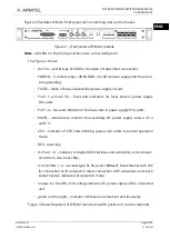
Figure 2 illustrates IPN-8U front panel with monitoring and control means.
Figure 2 – Front panel of IPN-8U module
Note
– All LEDs on the front panel have two colors (red/green).
The Figure 2 shows:
−
8х PoU
– socket type D-SUB for the cable of subscribers connection;
−
POWER – 3-contact plug «-48 0V GND» for 48 V power supply and the enclo-
sure grounding;
−
FUSES – block of fuses in subscriber power supply circuits:
−
PoU1 1-4, PoU2 5-8 – fuses and indicators for fuses state in power supply
PoU ports;
−
PoE 1-4 – fuse and indicator of the fuse state in power supply PoU ports;
−
MAIN – indicators to monitor the secondary DC power supply source 3,3 V
and 5 V;
−
CPU – indicator of CPU state; blinking green color refers to normal operation
mode;
−
RES – reset key;
−
8×PoU 1…8 – indicator of digital Uk0 interfaces and subscriber units connect-
ed to them, two-color LEDs;
−
4×PoE Ports 1…4 – sockets type RJ-45, ports 100BaseT Fast-Ethernet with PoE
for connection to IP-network or direct connection of IP subscriber units. Each
socket has two indicators of operation mode:
−
orange (on the left) –PoE voltage indicator for power supply of the connected
unit;
−
green (on the right) – indicator of Ethernet-connection and its activity.
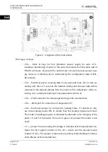
Figure 3 shows fragment of IPN-8U main board with position of control elements.

