ACM-IP2 ANALOGUE SUBSYSTEMS MODULE
User Manual
page 10/28
armtel.com
© Armtel
ENG
−
Х
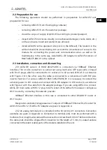
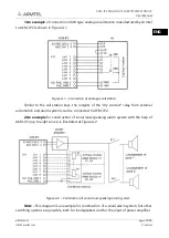
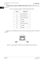
1, X2 – sockets for connection to Ethernet (including power supply by PoE plus);
LED indicators on sockets X1 and X2:
1.
Green – ON when there is physical connection with Ethernet network, blinking
when network interface is active (receiving or transmitting of data packages);
2.
Orange – ON when the unit is powered from the PoE source;
−
Х
3,
Х
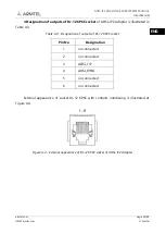
4 – sockets to connect analogue lines;
−
Х
8 – output socket of the integrated audio amplifier, (can be used, for example,
to listen to audio messages transmitted to terminal units);
−
Х
11 – socket of discrete lines (control lines), software configurable or as input
for connection, for example, direct call key of the terminal units or as output (for
load connection);
−
Х
19 – socket for external module ADSL-IP2 Adapter RMLT.468158.001;
−
Х
21 – socket to connect external power supply source, external power is
supplied to contacts 2 «-48V» and 3 «+0V». when the module is supplied by
РоЕ plus line, voltage is output to the same contacts 2 «
-48V» and 3 «+0V»;
−
Х
22 – negative potential on the load line, for example, the relay windings;
−
Х
42 – micro-SD card slot with card installed.
Each ACM-IP2 contains firmware and factory settings (IP address and MAC address).
To provide communication, IP network built using standard network equipment is needed.
Содержание ACM-IP2
Страница 2: ...armtel com Armtel info armtel com...
Страница 29: ...ACM IP2 ANALOGUE SUBSYSTEMS MODULE User Manual armtel com page 27 28 info armtel com Armtel ENG NOTES...
Страница 30: ...ACM IP2 ANALOGUE SUBSYSTEMS MODULE User Manual page 28 28 armtel com Armtel info armtel com ENG...
Страница 31: ...armtel com info armtel com Armtel...


