North America • Latin America • India • Europe / Middle East / Africa • China • Pacific Rim
armstrong
international.com
Designs, materials, weights and performance ratings are approximate and subject to change without notice. Visit
armstrong
international.com for up-to-date information.
8
Water Fill Supply
The humidifier can use any potable or purified water supply. Water pressure must be 25 – 125 psi
(1.7 – 8.6 bar). Water temperature must be less than 140°F (60°C). Average fill rates for all models is
3gpm (0.19 l/sec).
1. Install a shut-off valve near the unit.
2. Connect the water supply to the 3/8” NPT fitting on the fill water solenoid valve.
Electrical Service Wiring
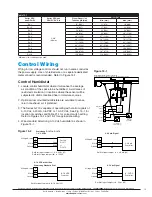
1. The control cabinet will require 120V 1ph supply to the terminals L1 and L2 in the cabinet.
2. A standard 120V 15A service is required.
3. The Series GFH must be electrically grounded in accordance with local codes, or in the absence of local
codes, with the National Electrical Code, ANSI / NFPA 70, and / or the CSA C22.1 Electrical Code.
Drainage
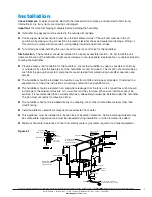
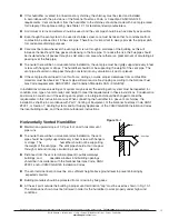
A ¾” connection is available to connect a 10” P trap to facilitate proper draining. Please see Figure 5-1 for
information. Average drain rates for all models is 3gpm (0.19 l/sec).
Gas Piping Selection
Caution:
Gas pressure to humidifier controls must never exceed 14” WC (1/2 psi). A 1/8” NPT plugged tapping,
accessible for test gauge connection, must be installed immediately upstream of the gas supply
connection to the appliance.
Installation of piping must be in accordance with local codes, and ANSI Z223.1, “National Fuel Gas Code,” or
CAN / CGA-B149 in Canada. Do not use flexible connectors.
Piping to unit should conform with local and national requirements for type and volume and gas handled, and
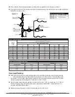
pressure drop allowed in line. Refer to Table 9-1 and 9-2 to determine the cubic feet per hour (cfh) for the type
of gas and size of unit to be installed. Using this value and the length of pipe necessary, determine the pipe
diameter. Where the same main serves several units, the total capacity, gas flow (cfh), and length of main
must be considered. Avoid pipe sizes smaller than ½”. Table 9-1 allows for the usual number of fittings with a
0.3” WC pressure drop.
After threading and reaming the ends, inspect piping and remove loose dirt and chips.
Support piping so that no strains are imposed on unit or controls.
Use two wrenches when connecting piping to unit controls.
Provide a drip pocket before each unit and in the line where low spots cannot be avoided.
Take-off to unit should come up from top or side of main to avoid trapping condensate.
Piping subject to wide temperature variations should be insulated.
Pitch piping up toward unit at least ¼” per 15 feet of horizontal run.
Compounds used on threaded joints of gas piping must be resistant to action of liquefied petroleum
gasses.
Purge air before lighting unit by disconnecting piping at gas control.
In no case should line be purged
into heat exchanger.
After installation, check field piping and humidifier gas train for gas leaks. Do not use soap solution on
humidifier gas train.
Install a ground joint union and a manual shut-off valve immediately upstream of the unit including a
1/8” NPT plugged tapping accessible for test gauge connection. Plugged tappings for test gauges are
located on all gas valves.

