13
How Duct Type Humidifiers Work
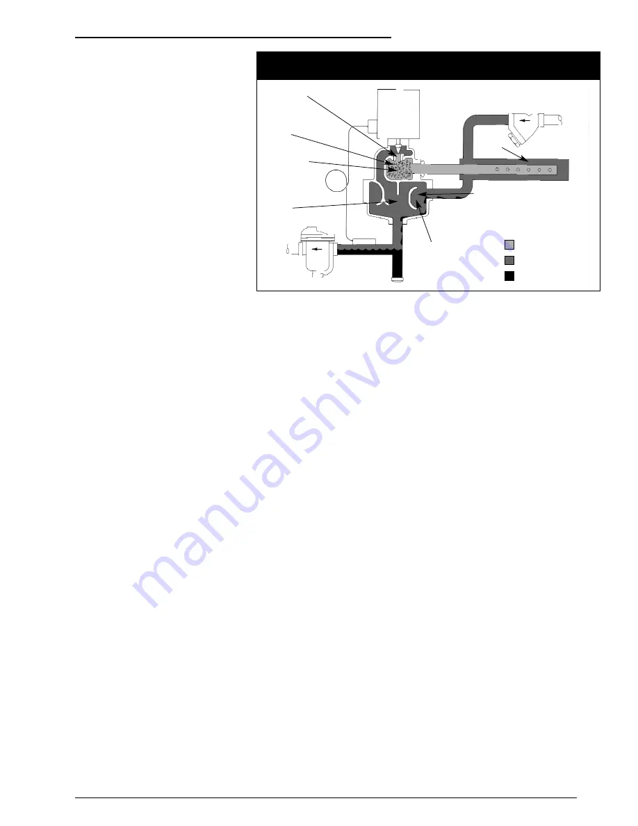
After passing through the Armstrong
inline strainer, steam supply enters the
steam jacket of the manifold and
circulates around the distribution pipe.
Steam now enters the cast iron steam
separating chamber. The use of cast
iron as a separator is probably the
single most important feature in the
Armstrong humidifier design.
The preferred material of strength and
durability, cast iron gives Series 9000
humidifiers flexibility in design without
fabrication. In addition, castings mean
better heat retention because of
thicker walls. Which in turn means a
lower rate of condensation.
Entering the main separating chamber,
steam encounters a cupped baffle
which reverses its flow and turns it
back on itself. The outer walls of the
casting form another cup, and the
same thing happens again. These two
180° turns help condition the steam,
reducing its volume and separating the
condensate from the vapor.
Condensate from supply and radiation
and most of the particulates in the
steam not removed by the strainer
collect in the large drain leg and are
discharged through the inverted
bucket drain trap.
Steam from the separating chamber
flows around and through the valve
which is actuated by a demand signal
from the humidistat.
Next the steam flows into the drying
chamber which is jacketed by the
separating chamber. The drying
chamber is filled with a stainless steel
silencing material which almost
completely absorbs the noise of
escaping steam
How air-operated units work.
Air-operated units operate in the same
manner as electric units except that
they utilize a pneumatic humidistat as
humidity controller in the space and an
air operator to open and close the
steam valve.
Explosion hazard
humidification.
Sizing air-operated humidifiers for
areas where an explosion hazard
exists is done exactly as for other
requirements except that they should
be sized for the most severe
conditions of makeup air, RH required
and minimum steam pressure.
Putting the Humidifier
Into Operation
When Temperature Switch Is
Employed simply set humidity
controller at desired level, and turn on
the steam.
When Temperature Switch Is Not
Employed deactivate operator control
so that humidifier control valve will
remain closed. Then:
A. Open steam supply valve to bring
humidifier up to temperature.
B. When drain line from humidifier is
at steam temperature, activate the
operator control.
C. Set desired relative humidity.
After the Humidifier
Is In Operation
Clean Strainer. The screen in the
strainer installed in the steam supply
line should be cleaned a few days
after the humidifier is placed in
operation, and thereafter at least once
each season—more often if you find
much dirt in the screen.
Check Trap. The steam trap used to
drain the humidifier should be
inspected at the same time the
strainer is cleaned.
Trouble Shooting
Humidifier Will Not
Discharge Steam
A. Control System at Fault.
1. Faulty control valve operator.
2. Faulty humidity controller.
3. Faulty connections between
humidity controller and control
valve operator.
B. Steam System Malfunction.
1. Silencing chamber plugged with
dirt. Remove and replace
silencing material and retainer.
2. Strainer screen plugged.
3. Dirt in steam line.
4. Steam valve closed in line to
humidifier.
5. Pressure reducing valve out of
order.
Humidifier Discharges Water
A. Faulty Steam Supply.
1. Long, untrapped suppy line.
2. Humidifier supply from bottom or
side of steam header.
3. Untrapped valve in vertical,
down feed supply line.
4. Boiler carryover.
B. Faulty Drainage.
1. Steam trap filled with dirt.
2. Return line pressure above
humidifier pressure.
3. Too much vertical lift.
4. Wrong type of drain trap used.
Always use the Armstrong
Inverted Bucket Steam Trap.
C. Faulty Operation.
1. Faulty temperature switch.
2. Humidity controller set up before
humidifier has reached steam
temperature.
Humidifler Discharges
Continuously even though
humidity has reached desired level.
A. Humidity controller out of
calibration.
B. Trouble in Humidifier
1. Valve stem “frozen” to stem seal
due to unusual chemical or
corrosive conditions in steam
system.
2. Operator spring broken.
3. Dirt or scale between valve and
seat.
Operating and Servicing
Figure 13-1. How Armstrong Conditioned Steam Humidifiers operate for air handling
humidification
Steam jacketed valve
positioned by
controller
Silencing
chamber
Steam jacketed
drying chamber
Separating
chamber
Abrupt change in
flow
Condensate formed in
supply line knocked
down by baffle
Steam at supply pressure
Steam at atmospheric
pressure
Condensate
Steam
jacketed
manifold
Steam supply


