background image

19

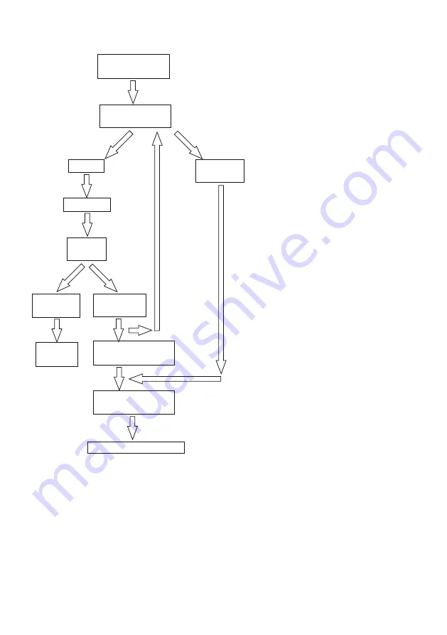
Fitting Field Test Audit (FC2)

go to commissioning FC1 (9.2)

2nd instance

follow maintenance

instructions (section 12)

1st instance

reset, follow 

setting instructions

accept

& record

mixed temp.

same as at

commissioning

2.0 C

±

º

deviation from

previous >+2.0ºC

check mixed

temperature

restore cold

pass

fail

see 12

undertake the cold

water isolation test

see 9.5

water supplies same as

previous audit or 


∆t change >5ºC

9.5 

In-field ‘Cold Water 

Isolation’(CWI) test.

Note: To gain access to the cold water 

isolating

valve, unscrew the right hand shroud & 

slide forward to expose the isolating

screw on top of the cold inlet leg.

Using a 5mm Allen Key, The isolation plug 

can be screwed down fully to isolate the 

cold water supply

Prior to commencing the CWI test, ensure:

1. The water supply conditions are met

    either:

A. For commissioning a new product

    (see table 1, section 4).

B. Or the inlet ∆t is within ±5°C to when the

    product was commissioned (see 9.4).

    NOTE It is important that the hot

    temperature is greater than 55°C

2. Mixed water outlet temperature is

    correct (see table 2, section 10).

To perform a CWI test, operate the product

using the sensor. Then conduct the follow-

ing procedure:

1. Record the steady state temperature of

    both hot and cold water supplies.

    Note the ∆t.

2. Record the temperature of the mixed

    water at the outlet.

3. Isolate the cold water 

    supply & monitor the flow of water from

    the outlet.

If the flow ceases, CWI test passed:

  1. Restore the cold water supply by rotating the isolator screw 90° clockwise.

  2. Slide the shroud back & screw onto the wall plate.

  3. Re-check the temperature of the stabilised mixed water at the outlet to ensure it is still correct.

Accept & record mixed temperature.

If there is an ongoing flow of water from the mixed water outlet, then 5 seconds after CWI collect the 

discharging water into a measuring vessel for 60 seconds. To pass the CWI test the volume of collected 

water should be less than 120ml.

If the product fails CWI test, see FC2 (section 9.4). Follow product maintenance (see section 12) and 

servicing (see section 10) instructions.

Содержание A6684AA

Страница 1: ...tector this black out lens cover should only be removed from the sensor after completing installation at least 20 seconds after powering up See page 3 for more details A6737AA Markwik 21 panel moun ted mixer sensor operated timed flow demountable with fixed spout Armitage Bioguard outlet Markwik 21 Sensor operated thermostatic mixers INSTALLER After installation please pass this instruction bookle...

Страница 2: ...LD WATER ISOLATION CWI TEST 19 9 6 SETTING TEMPERATURE FOR SENSOR OPERATED MIXERS 20 10 SERVICING TVM3 SCHEME 20 10 1 FREQUENCY OF REGULAR SERVICING 20 11 MAINTENANCE OF IN LINE COMPONENTS 20 12 MAINTENANCE 21 12 1 ADJUSTMENT OF THE MIX TEMPERATURE 21 12 2 REMOVAL AND INSPECTION OF CARTRIDGE 21 12 3 IMPORTANT NOTES ON DEBRIS 22 12 4 THERMOSTATIC CARTRIDGE AGEING 22 12 5 ARMITAGE BIOGUARD OUTLET 22...

Страница 3: ...ese products are in trinsically economical in terms of both water and electrical energy and will shut down in the event of a sensor being obstructed SENSOR PROTECTIVE COVER This product is supplied with the sensor lens covered over with a black out material DO NOT REMOVE this lens cover until the product installation has been completed then wait for at least 20 seconds after powering up The lens c...

Страница 4: ... right of the fitting but it can be mounted to the left if necessary They are both intended to be installed on duct panel walls The panel thickness should be in the range 13 27 mm Two holes of diameter 30mm nominal and one at 35mm nominal will need to be cut in the panel at centres defined in Figures 1 2 The hot side of the mixer is insulated to ensure the body surface is maintained at a safe temp...

Страница 5: ...hould be removed 1x Sensor kit complete 1x Velcro pad set 1x SV link cables pair 2x Inline service v a l v e s w i t h strainer 2x Solenoid valves 1x Power Supply Unit mains 2x Couplers G1 2 female thread to 15mm compression Fixing kit for mounting mixer Includes 2 off each back plates o rings slip washers back nuts ...

Страница 6: ... be mounted either side of the fitting In healthcare applications the height of the fixation holes above the waste appliance should be selected to create the recommended activity space as defined in HBN 00 10 Part C typically 150mm 200mm for a basin and 250mm 300mm for a surgeon s scrub up trough IMPORTANT Prior to installing mixer ensure that any existing thermostatic mixing valves TMVs that may ...

Страница 7: ...care establishments Effectively this means Differential between HOT and COLD inlet temperatures t must be 35C min and 60C max Differential between HOT inlet temperature and MIXED temperature t 14C preferred See 9 3 Audit checks on TMV s Note Fittings operating outside these conditions cannot be guaranteed by the scheme to operate as TMV3 This mixer is designed to be installed on all types of plumb...

Страница 8: ... aligned to 200mm centres in the wall See figure 1 for height positioning of the fitting body over a waste appliance The sensor will require a hole of 35mm positioned as indicated in either fig4 Loosen the chrome shrouds and insert the fitting as shown above with the wall plates and seals to the front of the wall Put on the slip washers and do up the backnuts to a torque of 25 Nm Screw the shrouds...

Страница 9: ...hod of assembling the plumb ing components Two of these assemblies are required per product OBSERVE ARROWS ON VALVE BODIES IMPORTANT Avoid using heat for soldering near the product inlets to prevent damage to internal components Mount mixer to the panel and secure the backnuts Fit swivel elbows 15mm x G1 2 not supplied to the inlet tails as shown and ensure the seals supplied with them are fitted ...

Страница 10: ...g service valves fitted to pipework supply pipes from above isolator screw filter access where access panel is available above product service valves can be orientated as shown supply pipes from above in line servicing valve should be orientated to permit easy access for maintenance FLOW Connect water supply pipes to the ser vice valves and make good all the joints Check that all connections are w...

Страница 11: ...to the purging port See 12 12 2 Screw the purging kit into the inlet port fully and then unscrew until the small indent on the purging kit towards the front of the inlet as shown 3 Open the isolating valve and allow water to discharge into a vessel until the water flows clean Suitable tubing can be push fitted onto the purging kits if required 4 Repeat on the both sides of the mixer so that the ho...

Страница 12: ...iring Regulations A typical example of an installation of a prox imity mixer is shown here as a guide Orientation position of solenoids and PSU Power Supply Unit case can differ from in stallation to installation An overview of the electrical wiring is shown in Fig 11 With the product securely mounted to the panel plumbed in electrical work can commence 7 INSTALLATION ELECTRICAL First connect the ...

Страница 13: ...ied This should be flexible 3A rated 2 core cable Carefully remove about 100mm of outer cable sheath ing strip the wire ends back by about 5mm Feed the cable through the grommet at the base of the case cut small slot in grommet first Connect the appropriate mains wires to the L Live N Neutral marked on the terminal block on the PCB Slide the PCB back into the case note guide slots allowing the mai...

Страница 14: ...uitable location on the rear of the mounting panel Note ensure the selected location does not stretch stress the cables Consideration should also be given to keeping the PSU case within easy reach access for maintenance staff Fasten the PSU case to the mounting panel This completes the behind panel installation work IMPORTANT Ensure terminal block screws are firmly tightened clamp the wires secure...

Страница 15: ...he LED will stop flashing and will stay fully on for about 5 more secs During this time move hand to required range up to a maximum of 250mm Leave hand at this position for 5 seconds the LED will start to flash again If it is necessary to change the run time go to Step 2 below otherwise move hand away from detection range The sensor now works normally and is no longer in programming mode If an err...

Страница 16: ...erly To start an audit log and record appropriate data This product is factory set at 40 1 C with supplies of circa 3 bar balanced pressure and temperatures of 15 C cold 65 C hot i e an inlet t of 50 a hot mix t of 24 For supply requirements see 4 0 Water supply conditions 9 2 Commissioning Process Establish that the supply conditions are within the requirements of HTM 04 and the supply conditions...

Страница 17: ...41 24 C pass accept record mixed temperature re set mixed to 41 C 0 2 C º follow setting or maintenance instructions MWT 41 C 0 º 2ºC check the supply conditions pressure 0 6 5 0 bar temperature 20ºC 55º record supply conditions and t for the hot cold investigate YES YES YES NO NO NO fail test undertake in field cold water isolation test see see 9 5 Achieved 41 0 2 C See section 9 6 setting temper...

Страница 18: ...ns are similar to when the product was commissioned i e inlet t as previous 5C Note If inlet t change is 5C consider the cause of the change If it is seen as a long term or permanent change re commission the product If however it is only a temporary change retest when normal conditions resume If inlet t differs from the commissioning t by 5C carry out field cold water isolation CWI test as D 08 20...

Страница 19: ...ee 9 4 NOTE It is important that the hot temperature is greater than 55 C 2 Mixed water outlet temperature is correct see table 2 section 10 To perform a CWI test operate the product using the sensor Then conduct the follow ing procedure 1 Record the steady state temperature of both hot and cold water supplies Note the t 2 Record the temperature of the mixed water at the outlet 3 Isolate the cold ...

Страница 20: ...tures The same type of measuring equipment should be used 2 If the temperature has changed significantly from the previously recorded valves the following should be checked a All in line or integral valve strainers are clear of obstruction b All in line or integral check valves are clean and working properly to prevent backflow c Any isolating valves are fully open d The thermostat is free of debr...

Страница 21: ... If you are unable to achieve 40 1 C and you have the correct t s it may be due to fine debris See 12 2 Removal and inspection of cartridge Upon successful completion of the temperature adjustment conduct the Cold Water Isolation CWI test See 9 5 to ensure product is working properly Refit the lock shield and record the mix temperature After checking that supply conditions are within the specified...

Страница 22: ...is greatly reduces the risk of bacteria build up whilst the copper lining has natural anti microbial properties Outlet is suitable for autoclaving In the interests of infection control and health hygiene the Armitage Bioguard Outlet is a supplement to not a substitute for standard infection control practices Continue to follow all current protocols includ ing those practices related to cleaning an...

Страница 23: ...tion refer to the programming instructions supplied with programming unit Keep hand unit away from the water flow avoid getting it wet Note Older handset units will display c SENSOR 2008 or 2003 by default Failed program output message will be i ERROR COMMUNICATION3 Latest handset can program all previous sensor versions 2013 2008 2003 a Handunit ON b Navigate to Menu 4 PARAMETER c SENSOR 2013 Ent...

Страница 24: ...side the valve body Clean out the pilot hole s use a thin gauge fuse wire or similar Ensure there is no debris on the diaphragm or the valve seat under diaphragm Re assemble solenoid valve Reconnect water supply check there are no leaks Reconnect the solenoid valve cables Test the solenoid valve ensure it is working correctly If diaphragm is damaged it should be replaced If the solenoid plunger be...

Страница 25: ...mer sion For disinfection solution see section 12 11 Sterilisation can be achieved by autoclaving for the desired period Complete spout can be autoclaved NB the seals can withstand this process Additional spouts are available so during cleaning protocols an alternative spout can be fitted while the original is removed This insures continuity of use of the mixer For additional spout part numbers se...

Страница 26: ...n appropriate method until required For disinfection solution see section 12 11 Method for demounting mixers 1 Isolate the hot and cold water supplies using the integral isolation valves See section 13 2 Undo the 2 grub screws securing the mixer using a 3mm hexagon key Take care not to lose the screws 3 Remove the mixer from the inlets by gently pulling away as shown Expect some trapped water to e...

Страница 27: ...f a damaged O ring Replace the seal as soon as possible as the mixer s safe touch thermal insulation feature will be compromised Front O ring seals Inlet legs removal If one or both inlet legs are removed from the panel for maintenance or repair then it is important to note the following ALIGNMENT Prior to installation both inlet legs must be securely fixed to the mixer body Fit the com plete asse...

Страница 28: ...ons will be derived from regular sampling carried out under the regime of the Responsible Person Water We would not expect to need greater than 6 monthly fre quencies hopefully considerably less The need for excessive use of this procedure would be indicative of the need for some root cause analy sis as there could be some system or behavioural problems that need addressing 12 11 Disinfection solu...

Страница 29: ...rs from the underside of the Inlets using a 5mm hexagon key 6 The strainers should be inspected and washed with clean water and can be Autoclaved or replaced as necessary 7 Before re assembling the strainers we recommend flushing the inlets with our purging and water sampling kit A6899NU not included 8 When refitting the strainers DO NOT OVER TIGHTEN observe torque setting shown below Removal and ...

Страница 30: ...sing suitable internal circlip pliers The CV FR can now be removed using long nose plyers however there is a high probability of damage during removal Ø12mm Intermal Circlip DIN472 Inlet IMPORTANT The CV FR s can be replaced but must not be removed The pink CV FR must be fitted to the cold water inlet Right side of the mixer when viewed from the front The yellow CV FR must be fitted to the hot wat...

Страница 31: ...ection 12 10 A6256AA Universal filter adaptor Replaces the Armitage Bioguard outlet to permit attachment of an outlet filter Threaded M24x1 internal F960970NU Remote programming unit See section A6252AA Panel mount spout complete Short version with100mm reach Fitted with Armitage Bioguard outlet o rings at the mixer coupling end See section 9 7 A6899NU Panel Flushing set See section 6 1 A6898NU De...

Страница 32: ...62477NU 2 Inline service valve with filter only E960086NU 3 SV coupler kit pair A962499NU 4 Solenoid valve with seals A962478NU 5 PCB only with transformer A960159NU 6 Velcro pad kit A860704NU 7 8 PSU Complete A962881NU Strainer O ring kit pair A861284NU 2 3 4 1 5 7 6 8 16 SPAREPARTS ELECTRICAL ...

Страница 33: ...33 17 SPAREPARTS 1 3 2 5A 5B 20 19 18 17 9 10 33 21 23 18 34 24 25 21 26 27 28 29 15 14 13 12 11 7 4 6 8 8 25 30 17 31 For complete spout subassemblies see section 17 5C 5D 32 16A B 22A B ...

Страница 34: ... 17 O ring 17 x 2 5 A963143NU 18 O ring Ø 24 x 2 A961809NU 19 Inlet insulator 20 Inlet Sleeve 21 Circlip Pack contains 4x parts A861346NU 22a Combined CV FR Ø10mm cold water pink right side A861215NU 22b Combined CV FR Ø10mm hot water yellow left side A861216NU 23 O ring Ø 12 42 x 1 78 A961332NU 24 Isolation plug cpl 2 sets A861329NU 25 O ring dia 8 1 x 1 6 single available within item 16 A962345N...

Страница 35: ...thermostatic mixer Demountable with fixed spout Armitage Bioguard outlet A6734AA Deck mount thermostatic mixer Demountable with fixed spout Armitage Bioguard outlet A6696AA Markwik 21 thermostatic basin mixer with copper inlet pipes Includes demountable body removable spout Bioguard outlet A6791NU Markwik 21 Back to wall connecting kit for closed wash basins ...

Страница 36: ...ge Gent Building Da Vincilaan 2 1935 Zaventem Belgium www idealstandardinternational com For more information about our products spares visit our websites www idealstandard co uk 18 CLEANING CHROME SURFACES When cleaning chromed products use only a mild detergent rinse wipe dry with a soft cloth Ideally clean after each use to maintain appearance Never use abrasive scouring powders or scrapers Nev...

Отзывы: